1952 Schramm Pneumapower 35 Compressor Rebuild
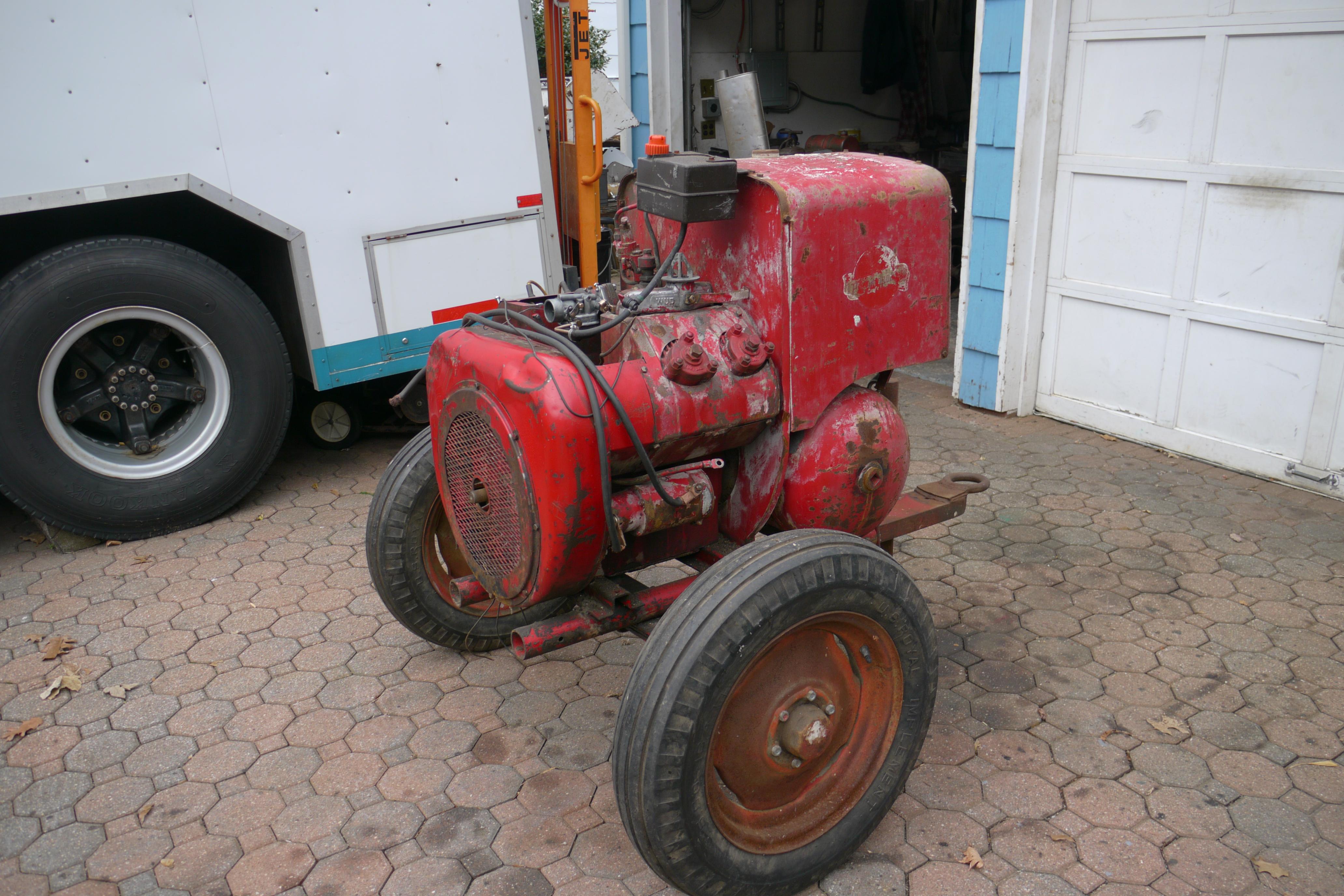
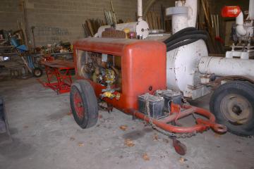
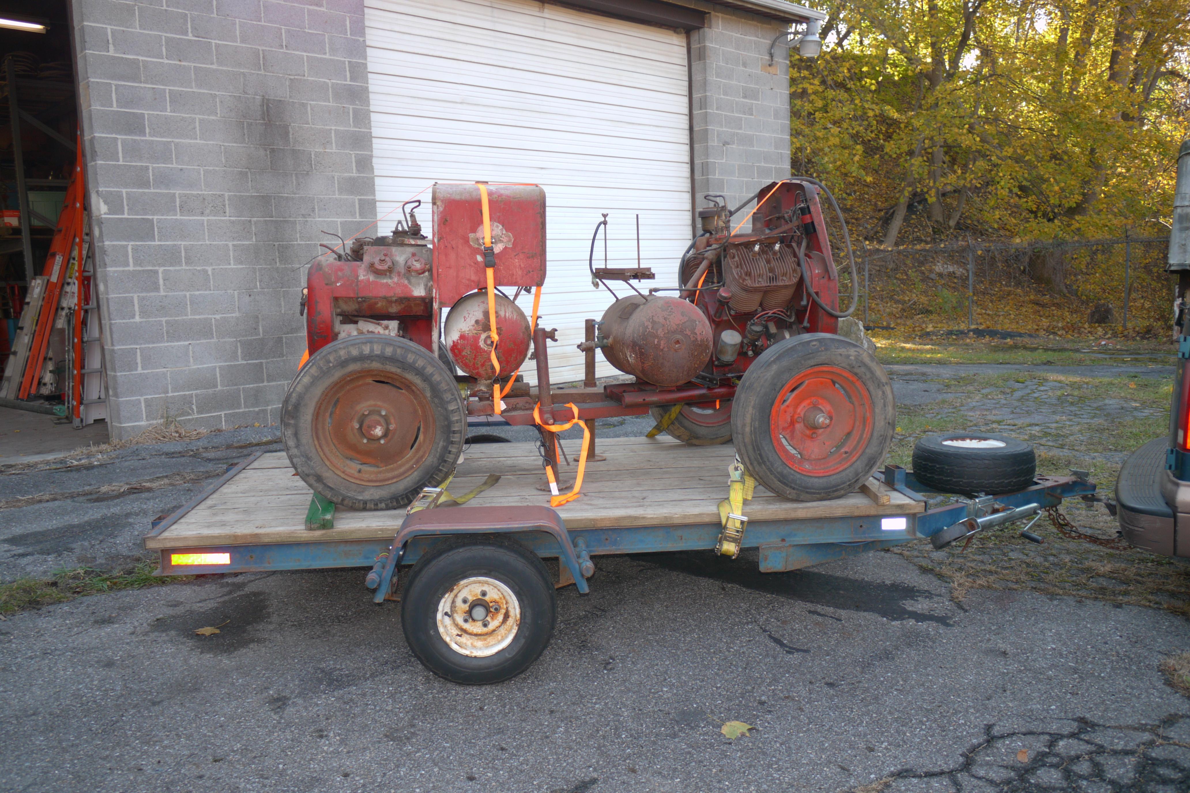
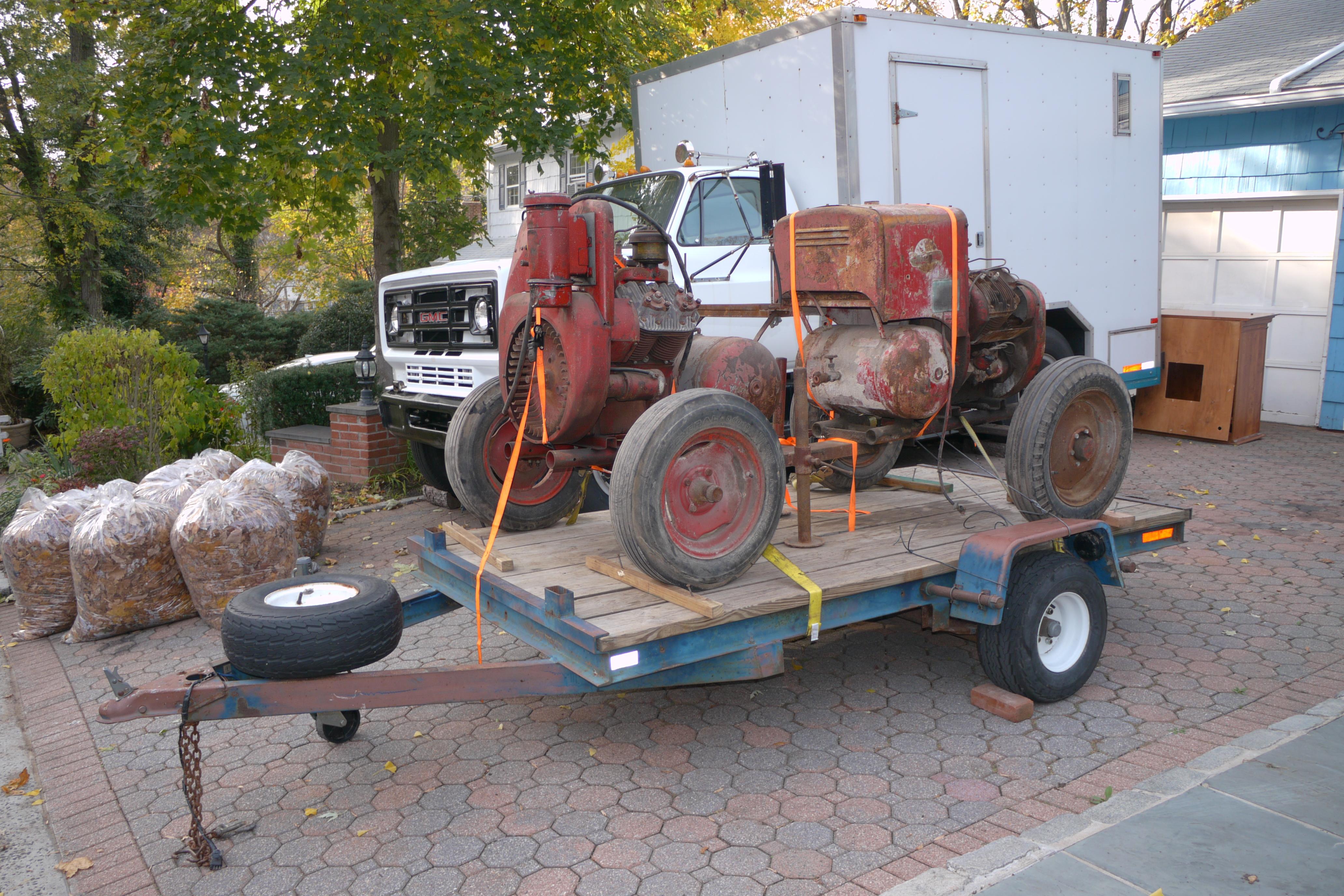
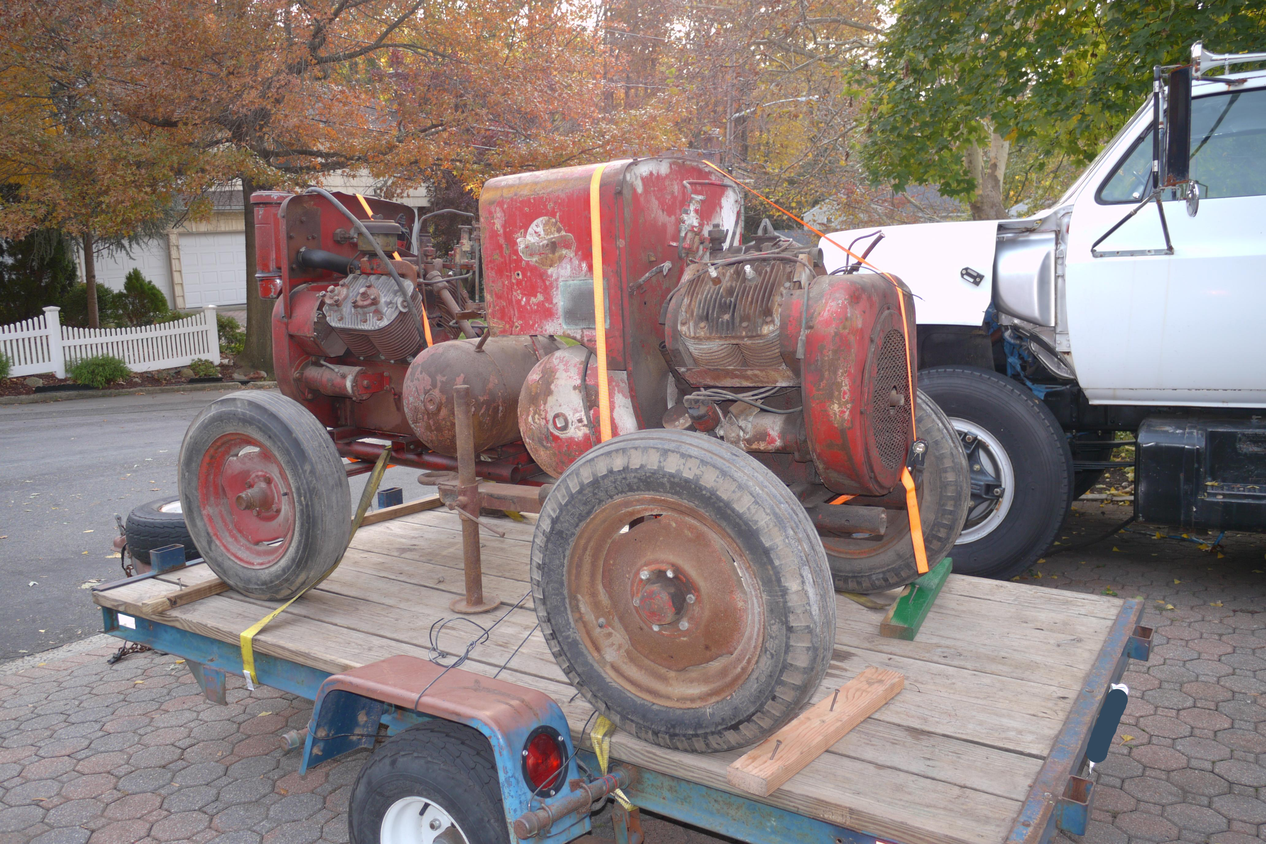
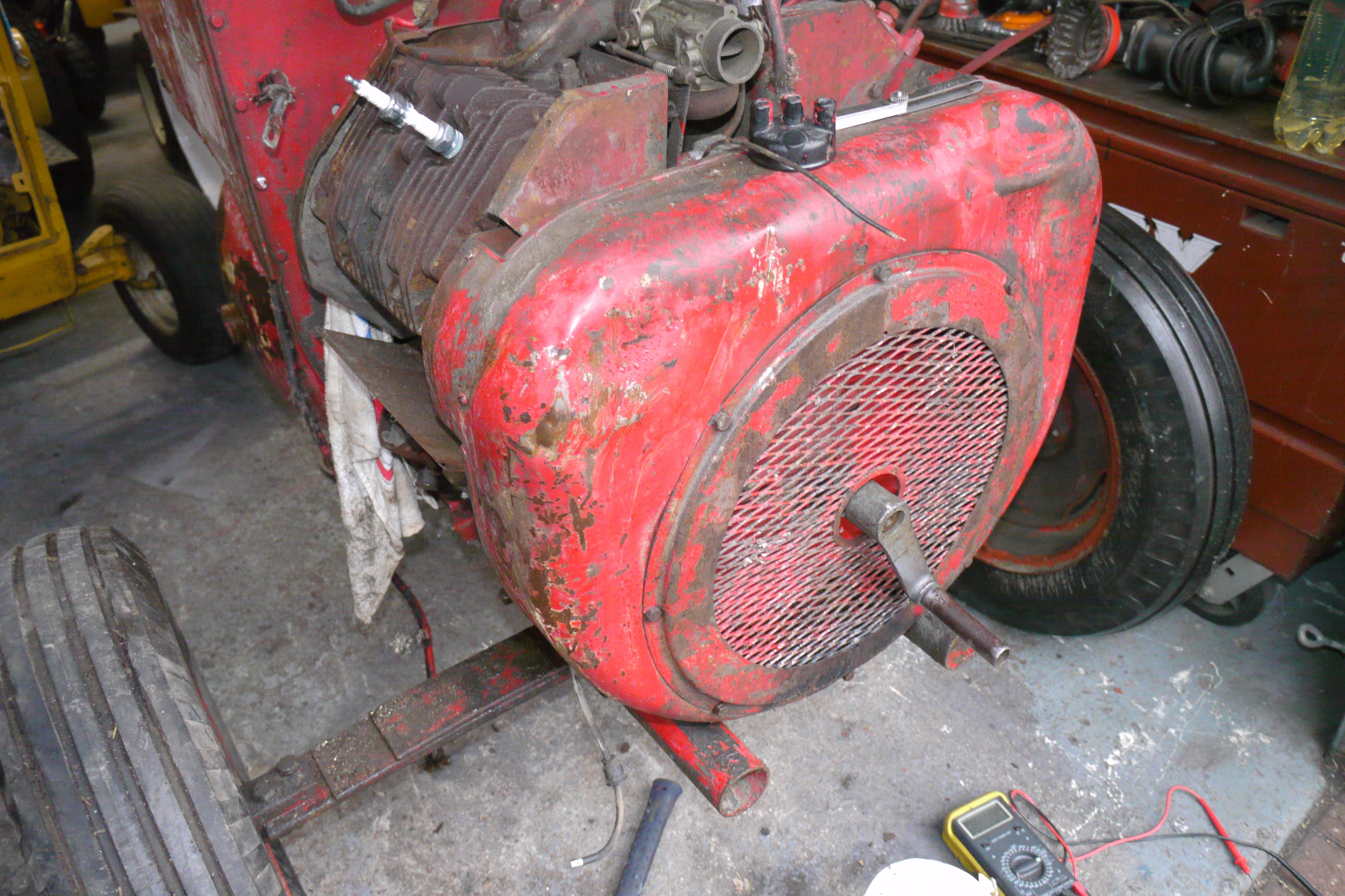
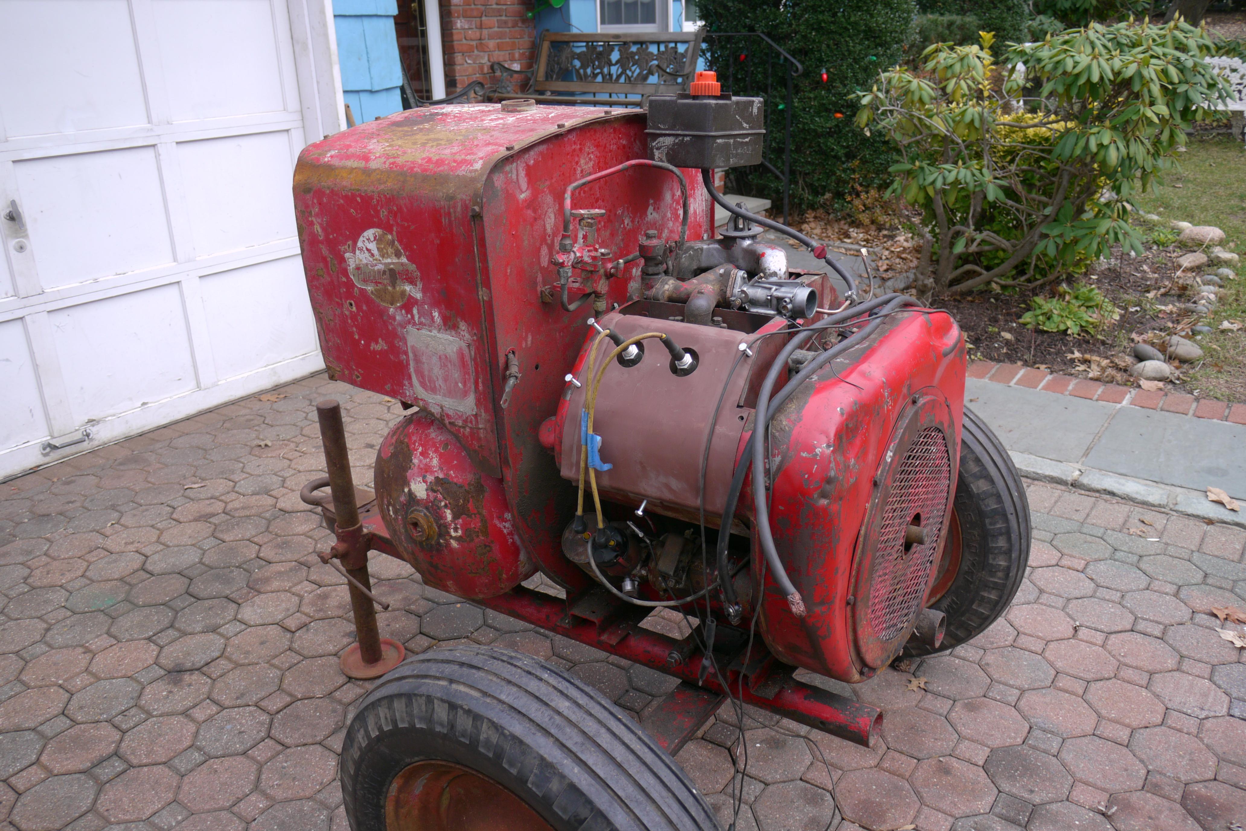
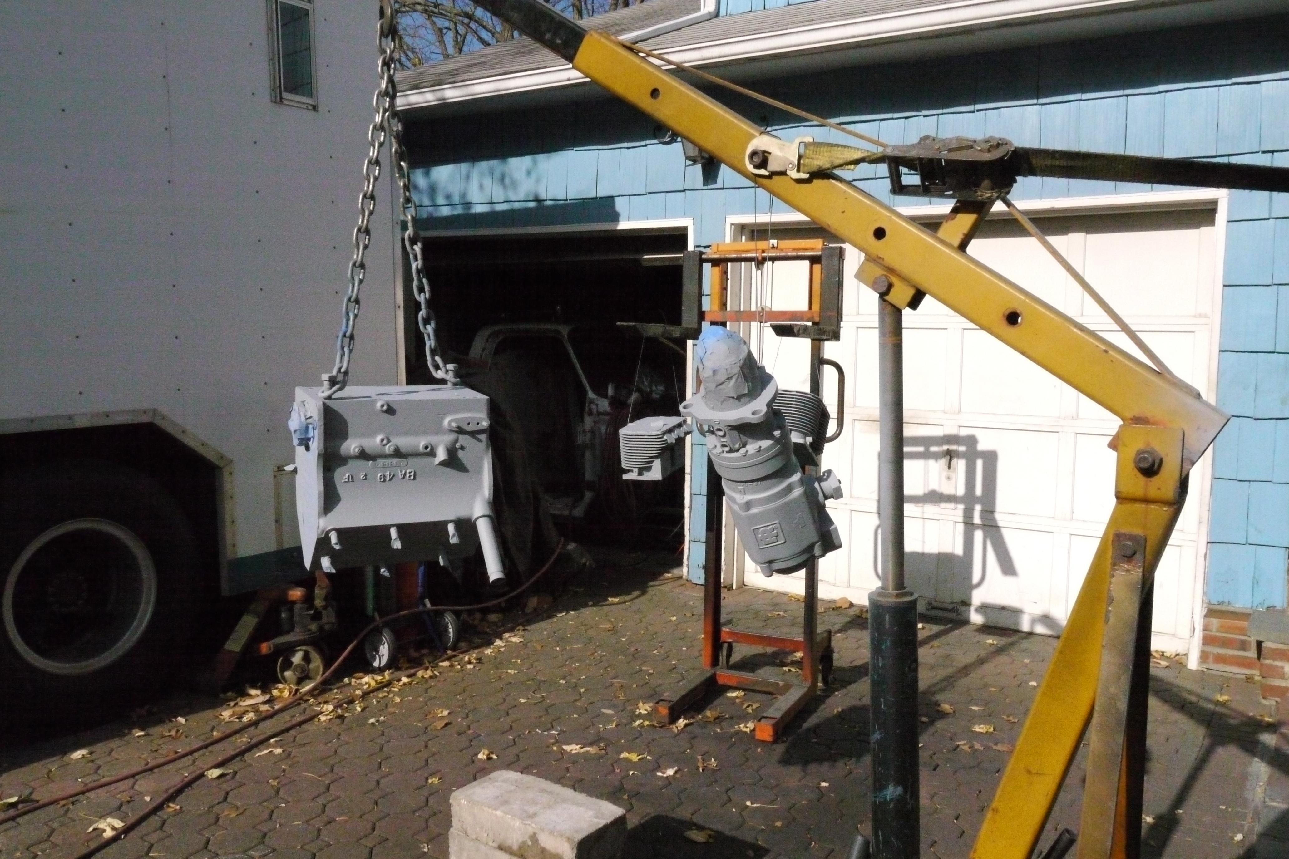
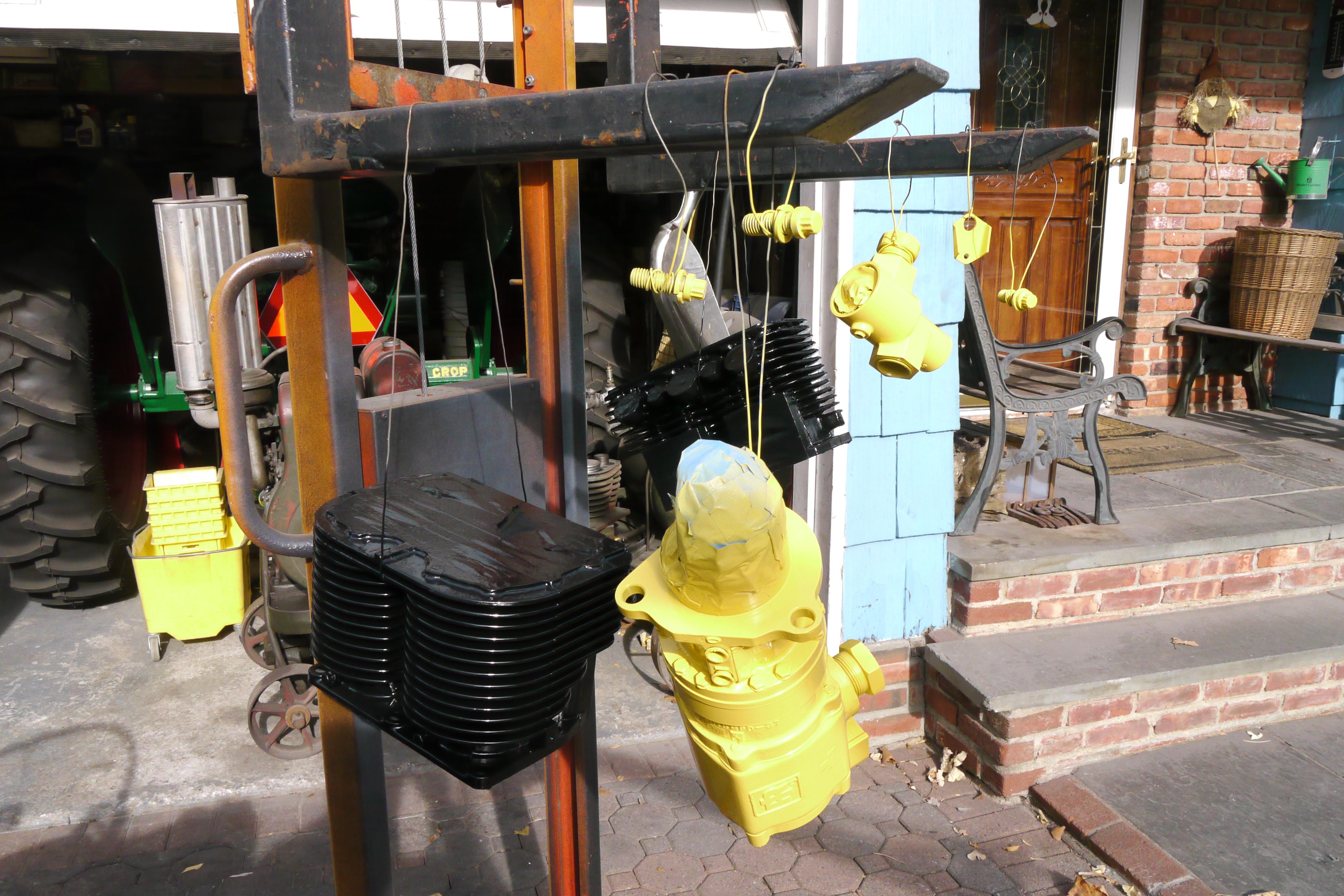
The Search for the Perfect Portable Gasoline Driven Air Compressor: In November of 2014, I traveled to Slatington, Pennsylvania to pick up a pair of Schramm Pneumapower 35 Compressors. At the time I had been looking for a compact engine driven air compressor for my truck project. This compressor would act as a backup onboard compressor to re-charge the air tanks on my truck should the onboard tanks run out of air before the engine starts. I had looked into a number of engine driven compressors, built by Devilbiss, Jenbach, Lindsay, Rolair and Sulair and could not find a compact solution which could deliver the volume of air that I was looking for. I stumbled across Schramm’s lineup of air compressors while looking for a Lindsay Compressor. I wanted a compressor driven by a heavy duty Wisconsin air cooled industrial engine, and Schramm had exactly what I was looking for. After searching the internet far and wide for information on Schramm’s products, I stumbled across their portable Pneumapower lineup. Schramm built two compact Pneumapower compressors, the “20” and the “35”. The “20” was a twenty cfm compressor built out of a Wisconsin VH4D engine with 3-1/4” bore and 3-1/4” stroke. The “35” was a thirty-five cfm compressor built out of a Wisconsin VP4 engine with a 3-1/2” bore and 4” stroke. I spent nearly six months looking for either the “20” or “35” Pneumapower compressors. I eventually stumbled across an ad on craigslist of these two Pneumapower 35 Compressors (see images below). Gail, the owner of the compressors was a lovely woman who explained to me the history of these compressors, and how her husband swore by them. He worked in the sandblasting industry and had a number of Schramm compressors in his collection. He had the intention of restoring these compressors before he died. Gail saw my ambition and yearn to finish rebuilding these compressors and gave me a wonderful deal on them. Both units had been set-up after sitting for a number of years, but that has never stopped me from purchasing a rare machine before. Both of the units were 90-95% complete, and everything I wanted for my truck project.
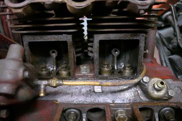
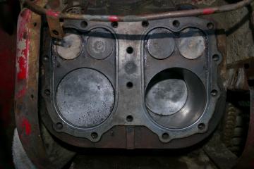
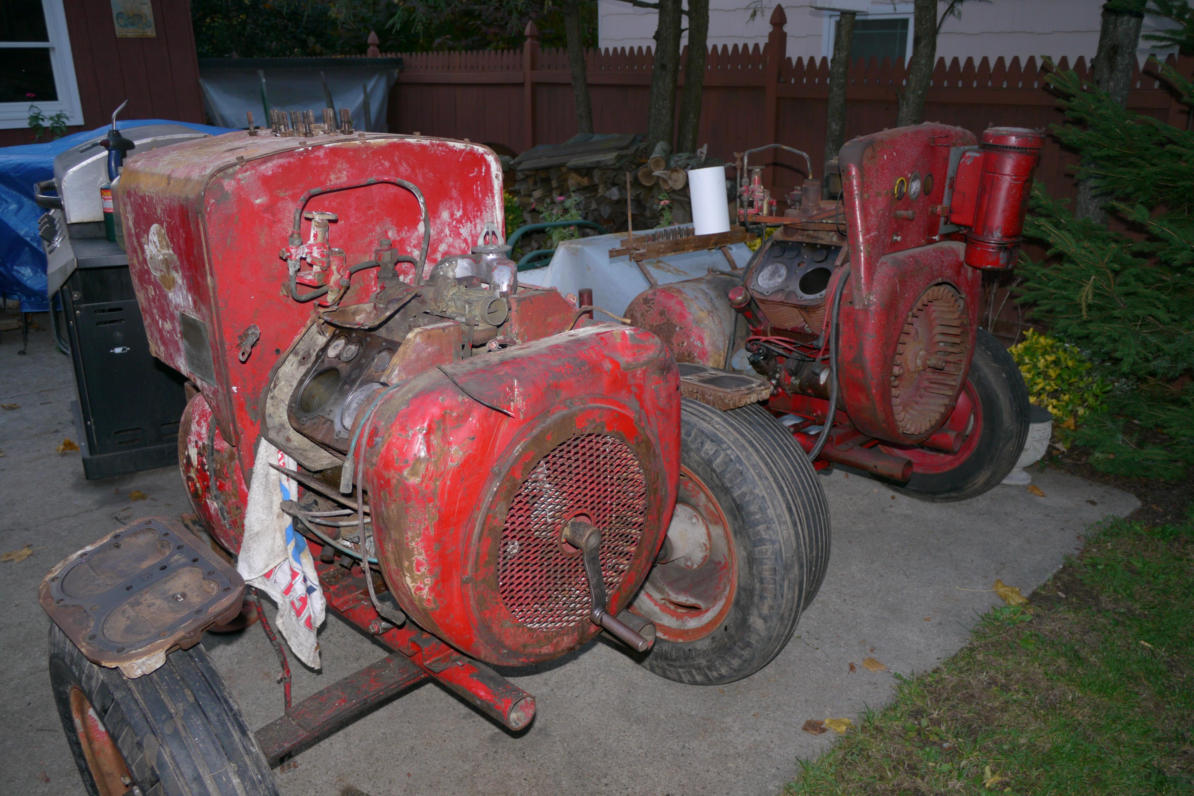
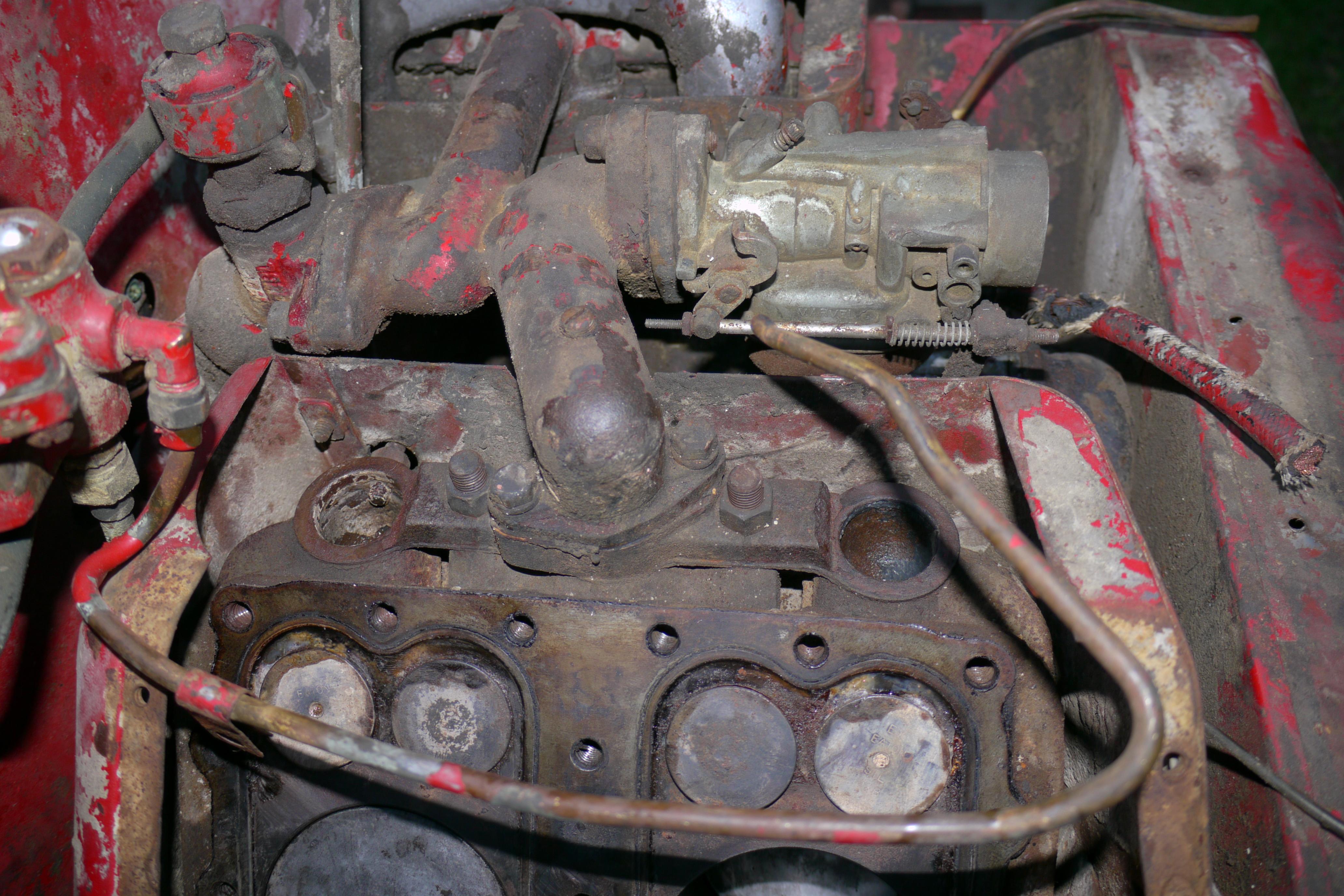
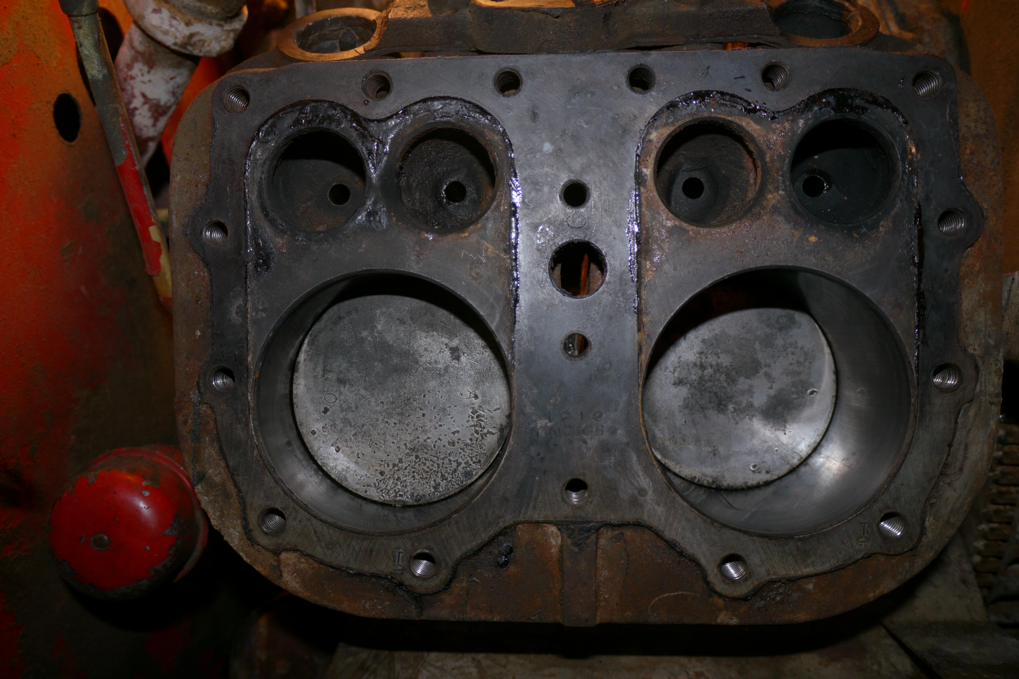
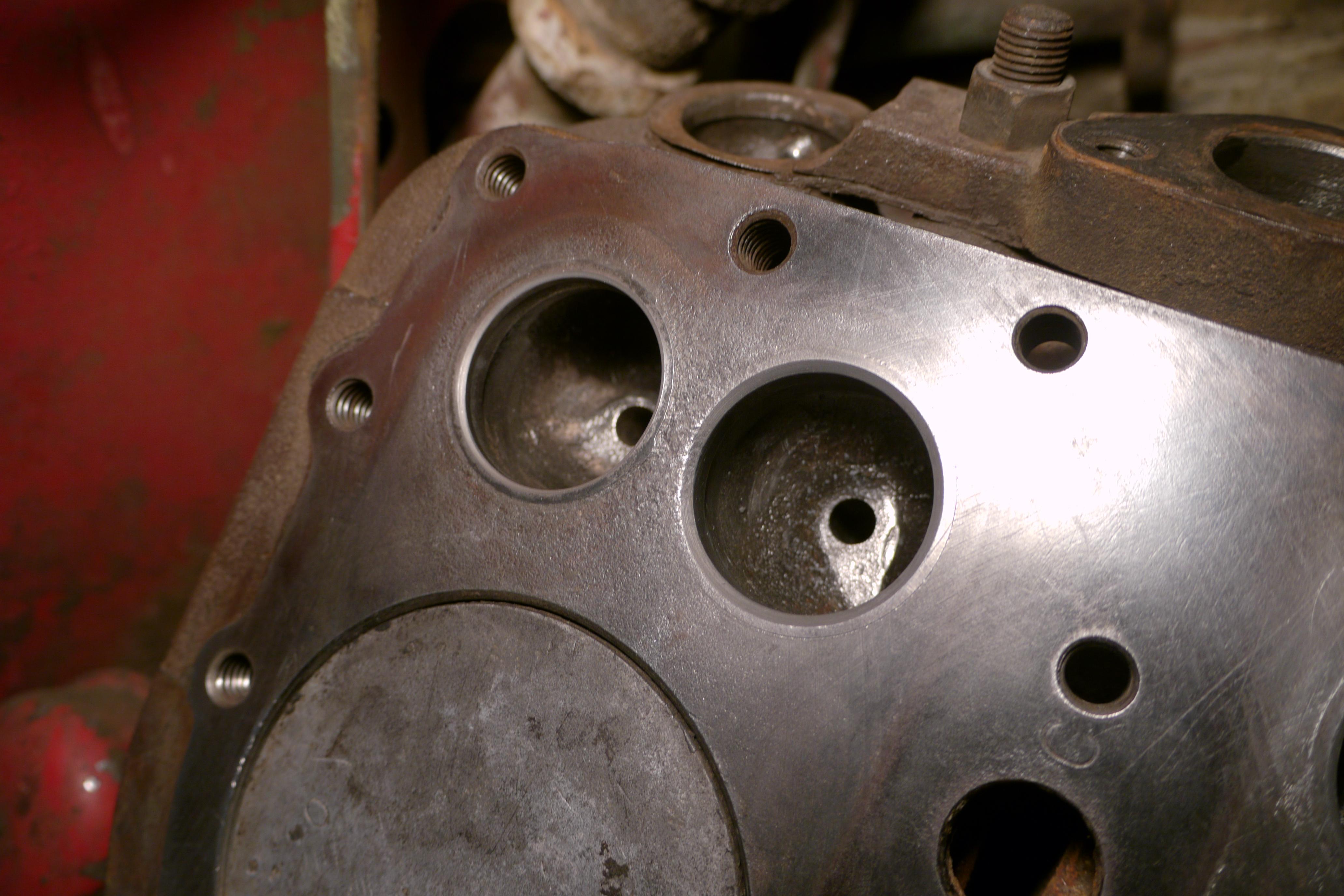
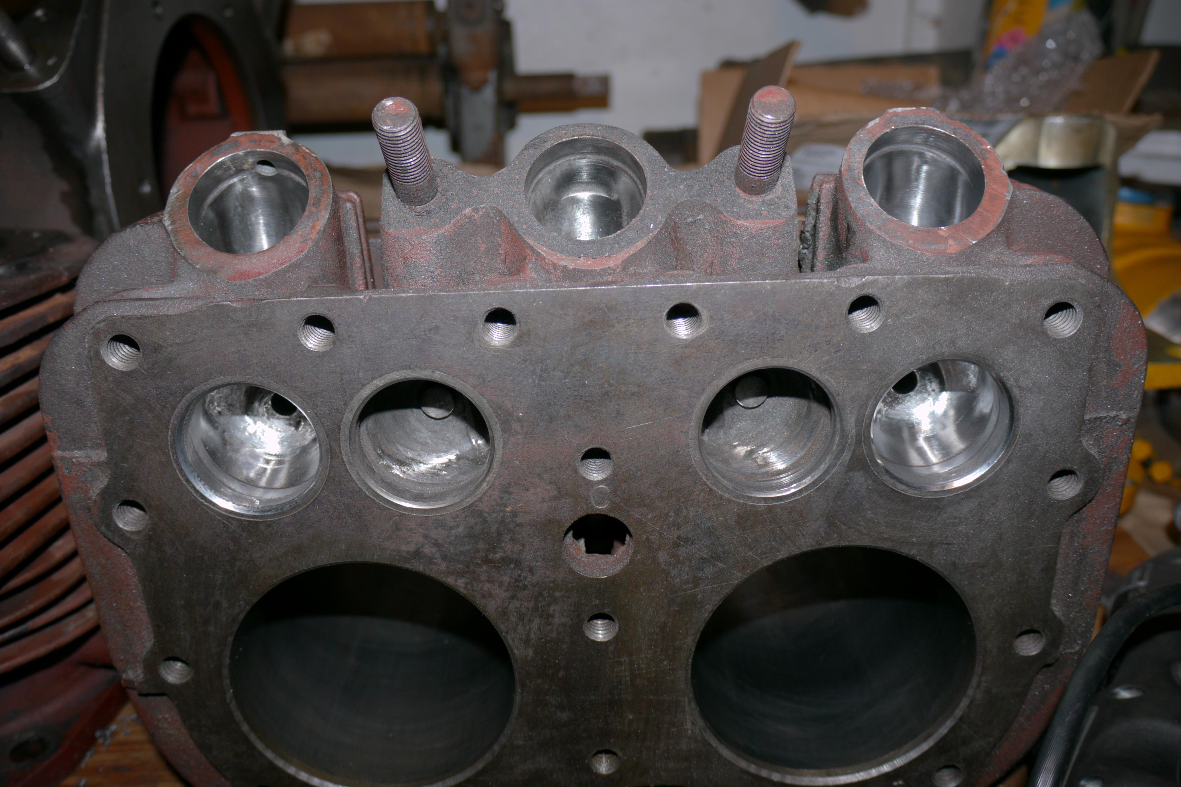
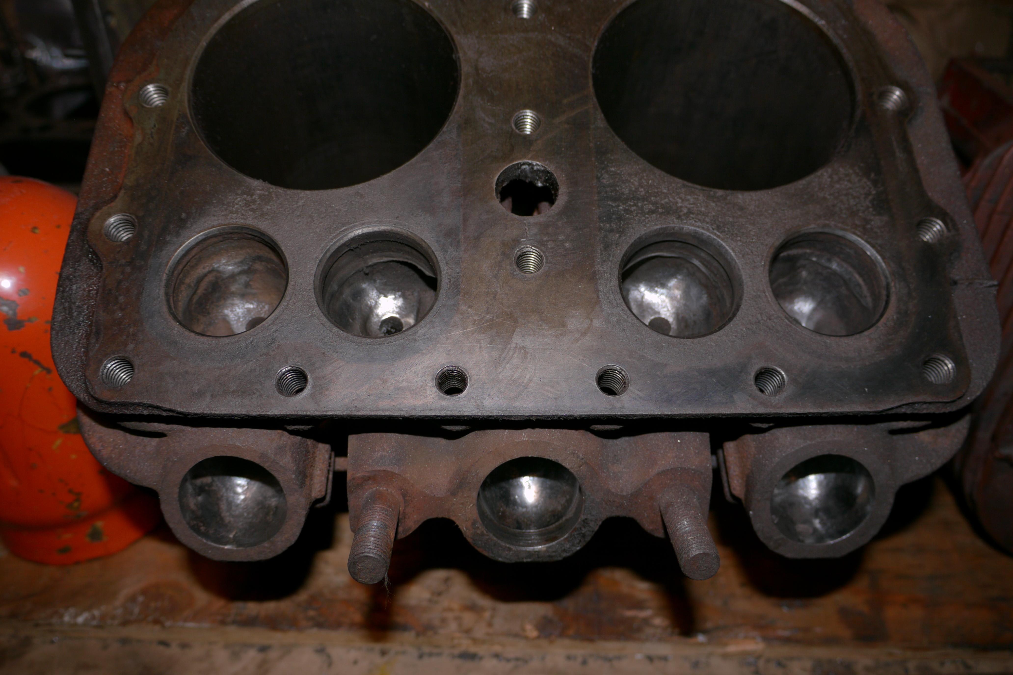
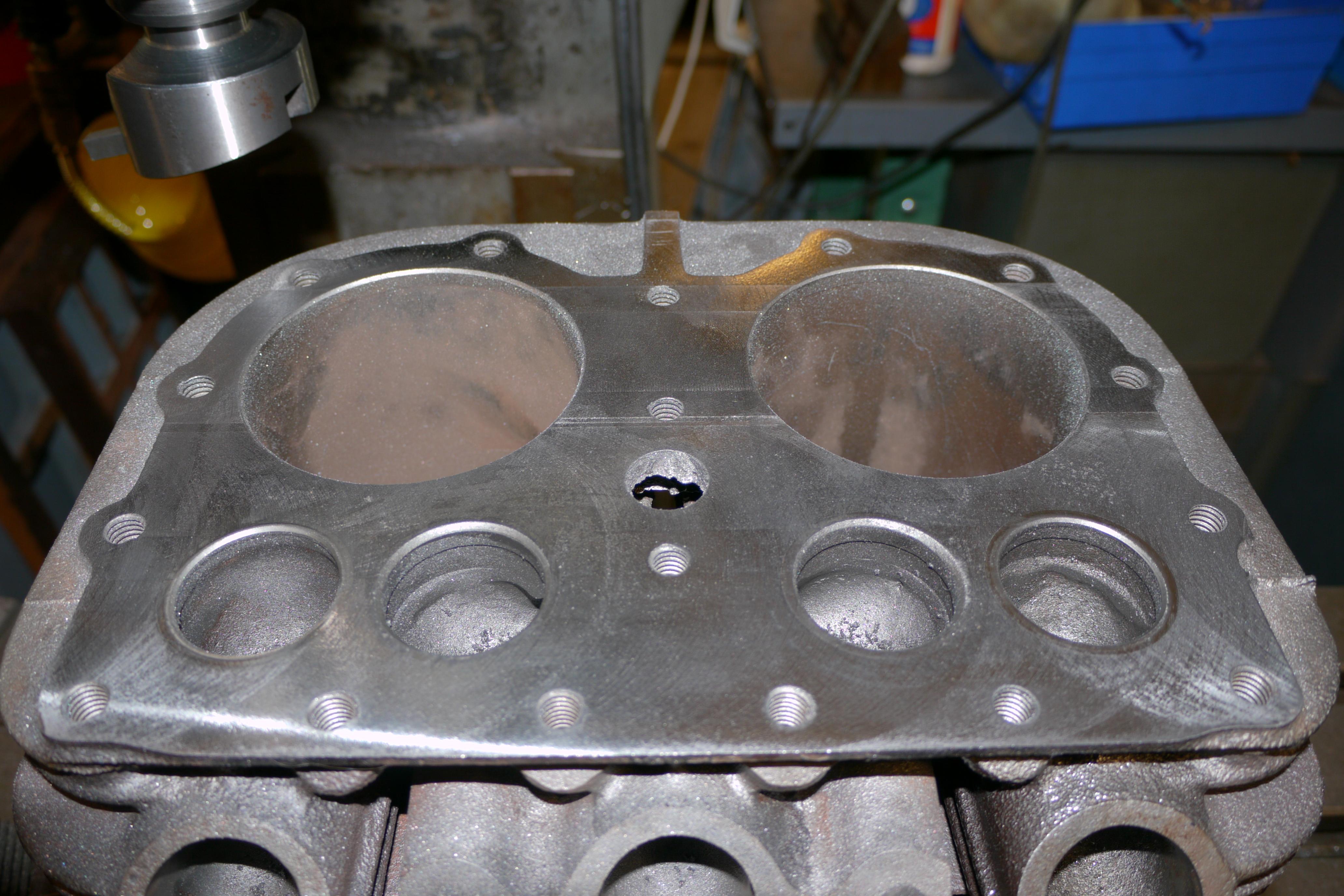
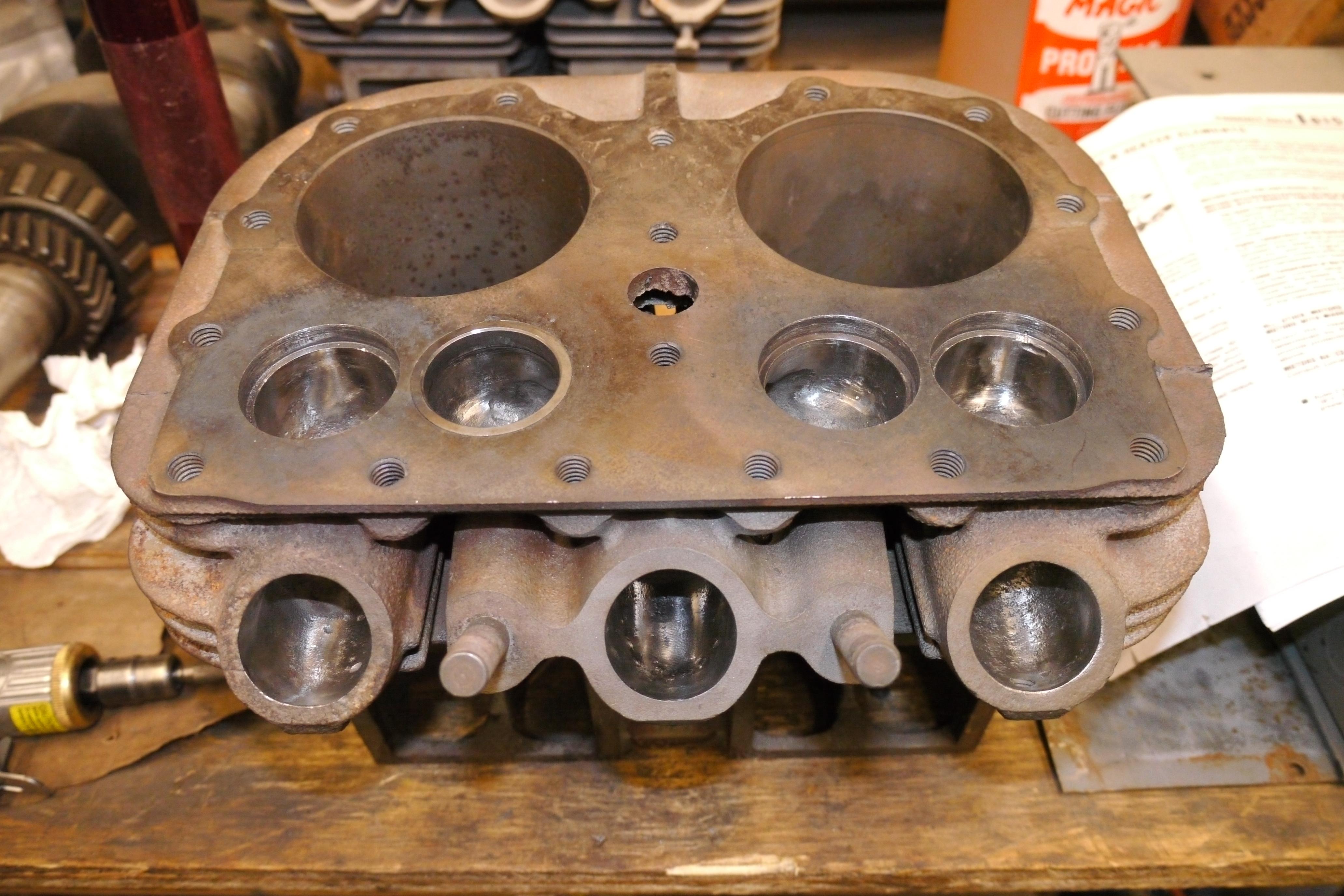
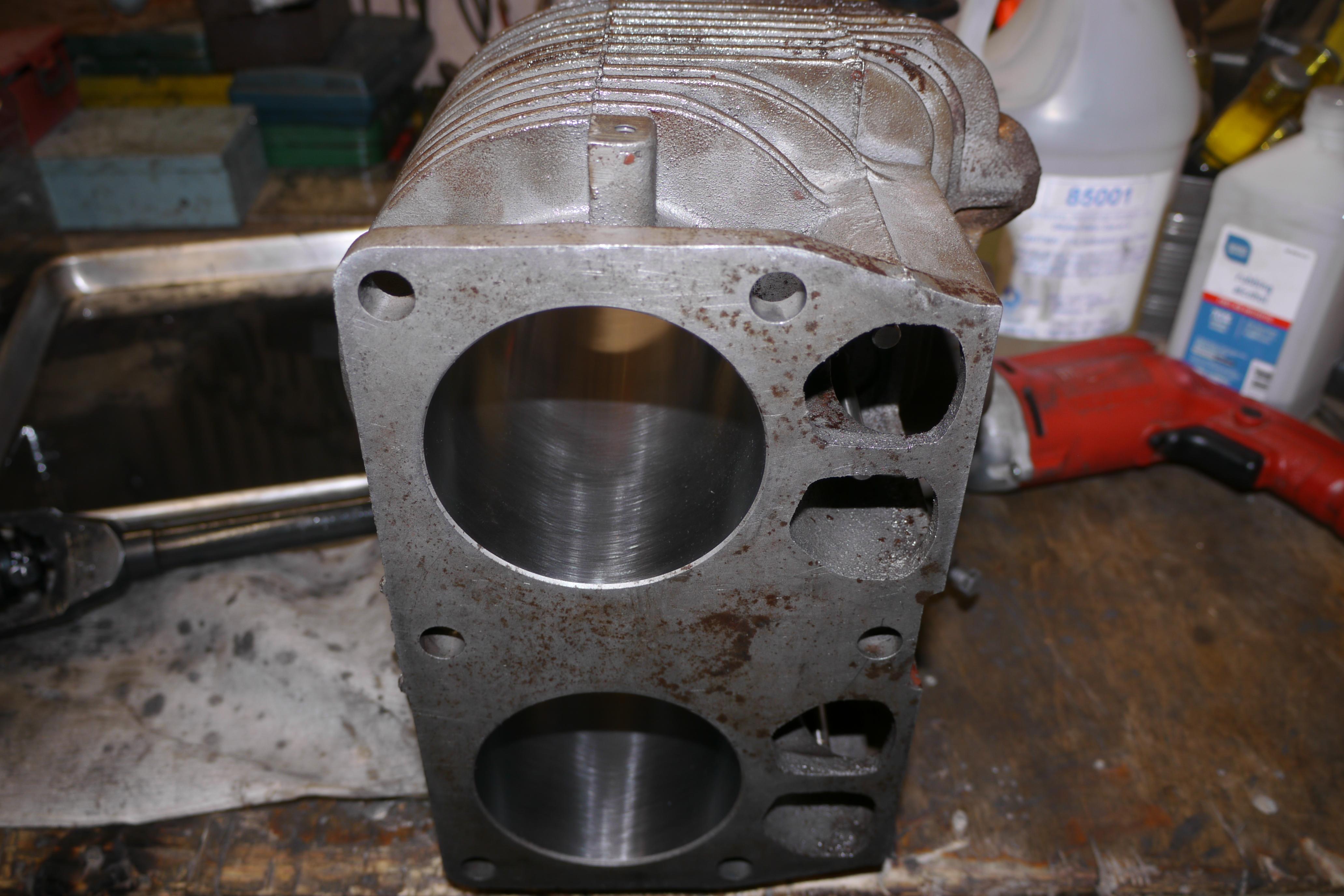
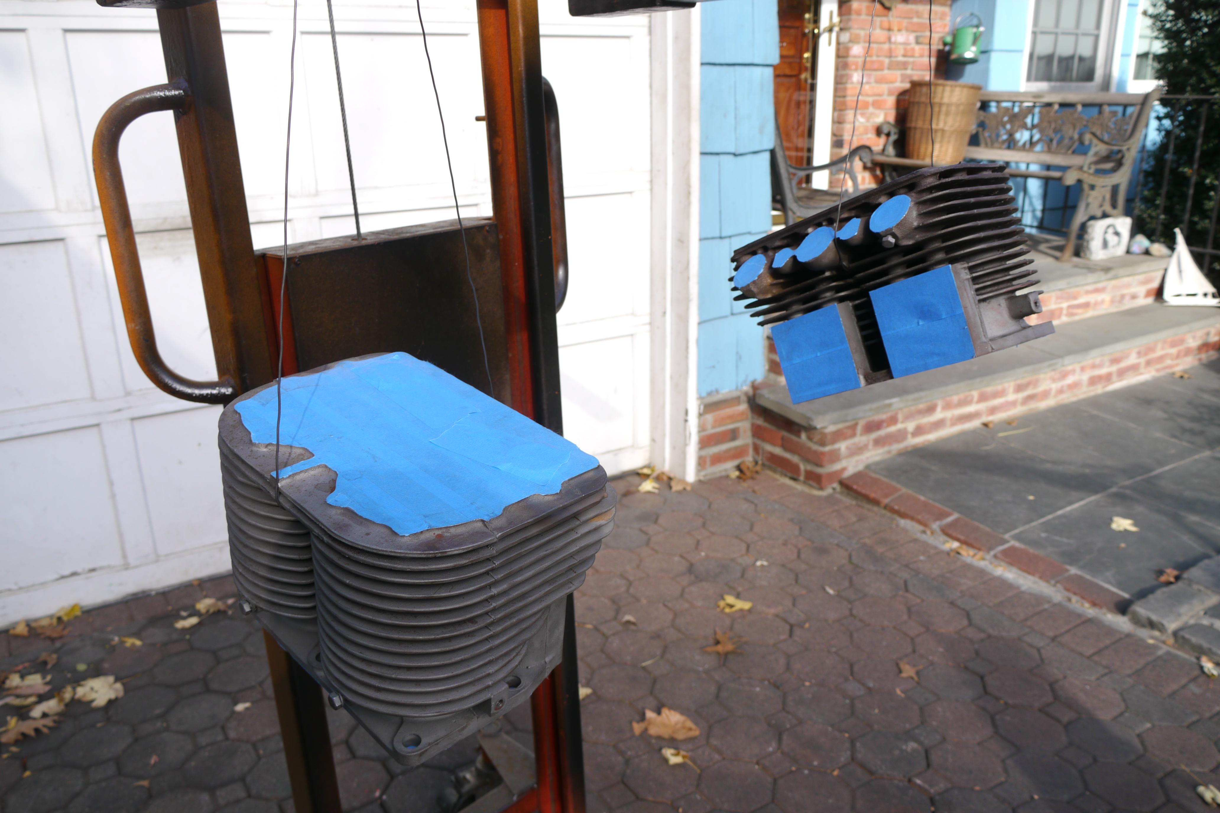
One of the units was clearly used more than the other and was covered in concrete dust. The first thing I did was power-wash both compressors to see what condition they were really in. Once dry, I proceeded to “free” the engines back up. Engines do not seize up overnight, so they usually do not free up very easily. The first step towards freeing up an engine is locating the seized part. In a flat head engine the typical seizure locations are; the pistons in their cylinders, the valves in their valve guides, or the piston pins in the pistons. Removing the cylinder head will give you a good idea as to whether the engine is seized in the cylinders, in the valves or in the bearings. Pulling the cylinder heads on this engine exposed the intake and the exhaust valves and loads of hard carbon and greasy/oil deposits on top of the pistons. In a four cycle engine there is only one time that all of the valves in a flat head four cylinder engine will be closed at the same time. Chances are one or more of the valves will be open. If an engine has sat for many years with either a carburetor or a muffler removed, with its respective valve open, you can almost guarantee that that valve has become seized in its guide. This particular engine was likely sitting for a decade before I purchased it, and in that time all of the valves had become sticky. Luckily they weren’t too seized up that I couldn’t remove them. A good thorough cleaning of the combustion chambers, valve heads, and piston domes will allow the penetrating oil to get into the crevices it needs to. I filled the cylinders with penetrating oil, and heated the cylinder jugs with a propane torch. Tapping the sides of the cylinder jugs with a rubber mallet when hot will help the penetrating oil get down between the piston and the cylinder. Surprisingly both of the engines free-ed up without too much trouble, indicating that the engines were simply dry-seized.
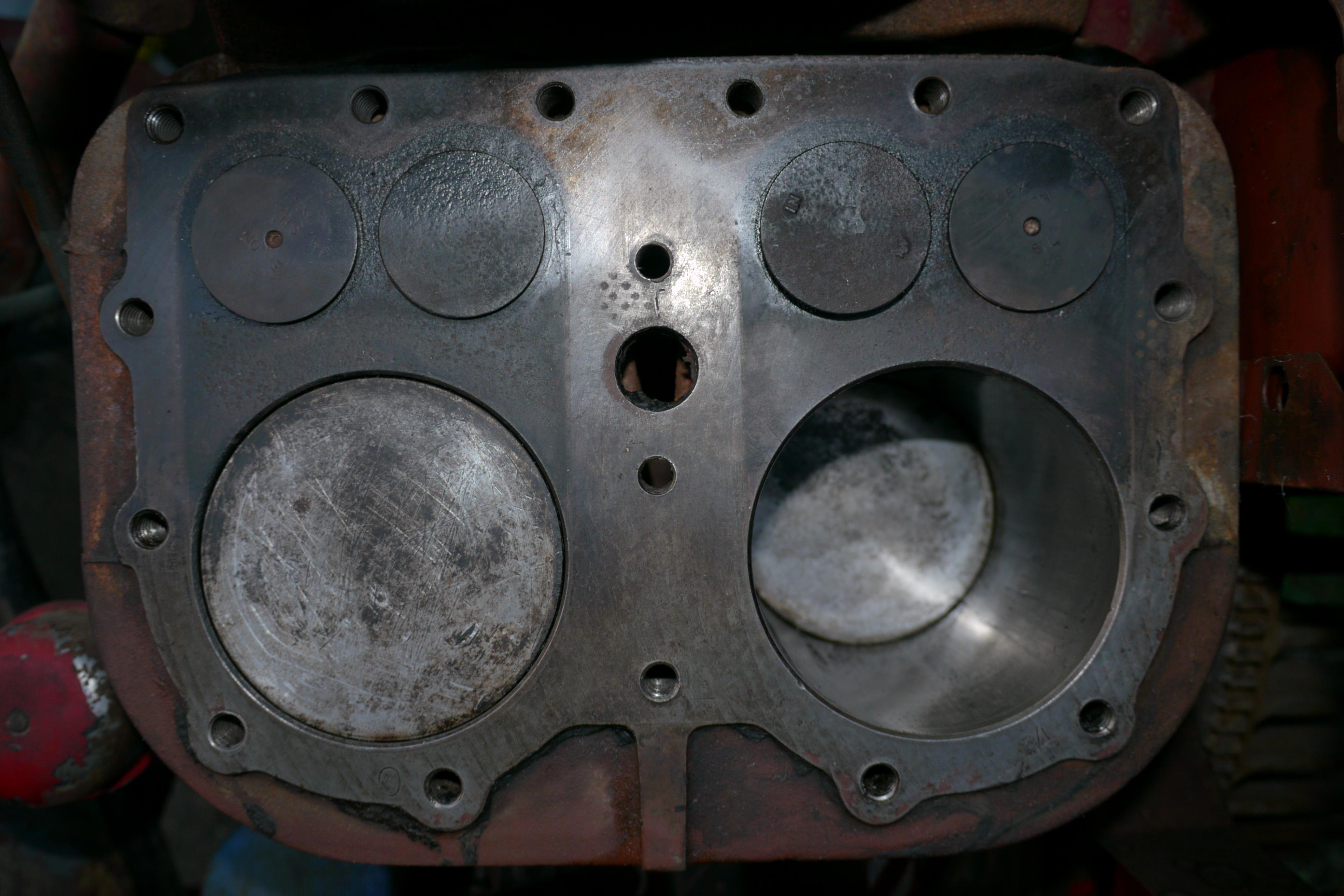
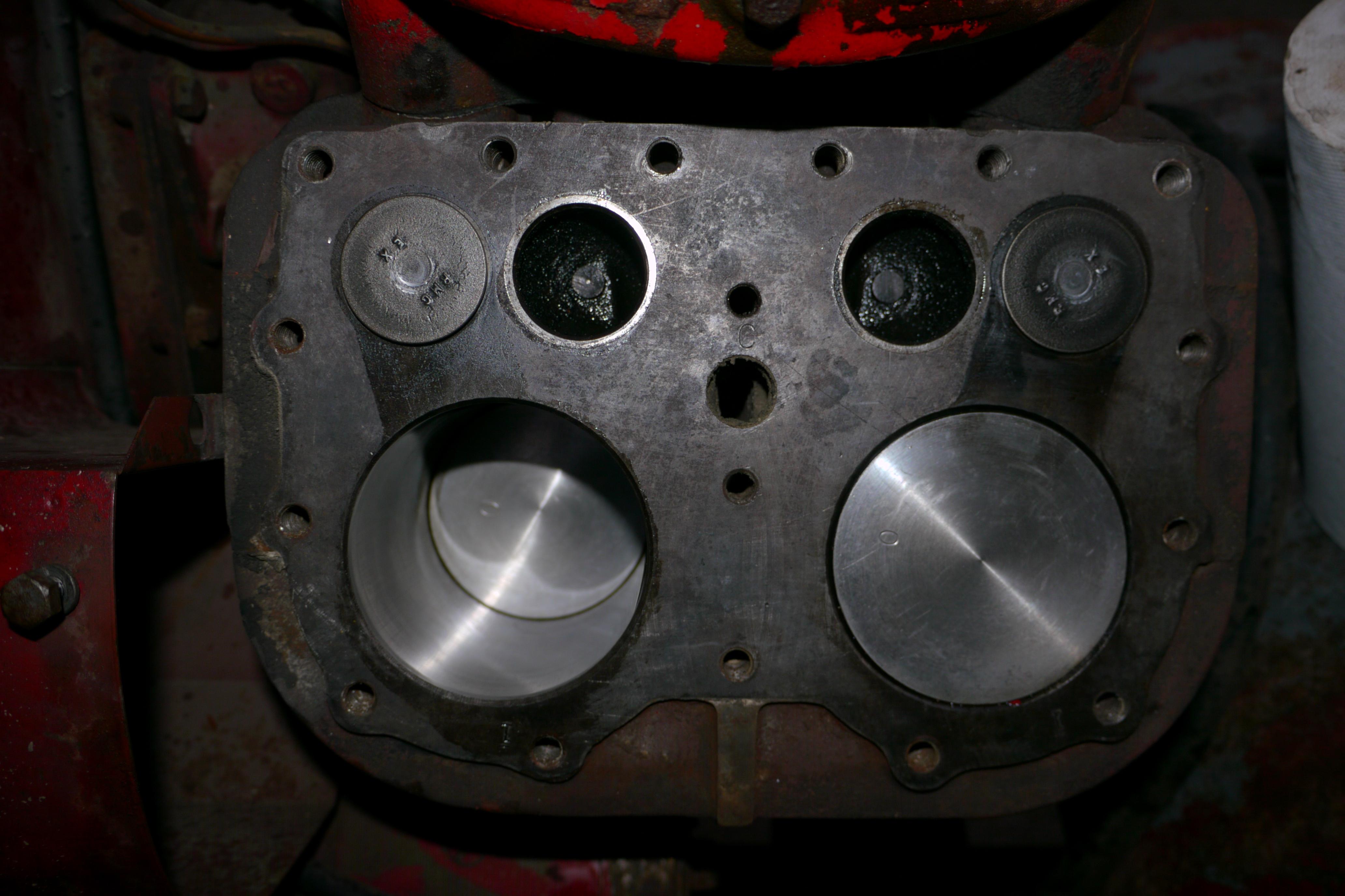
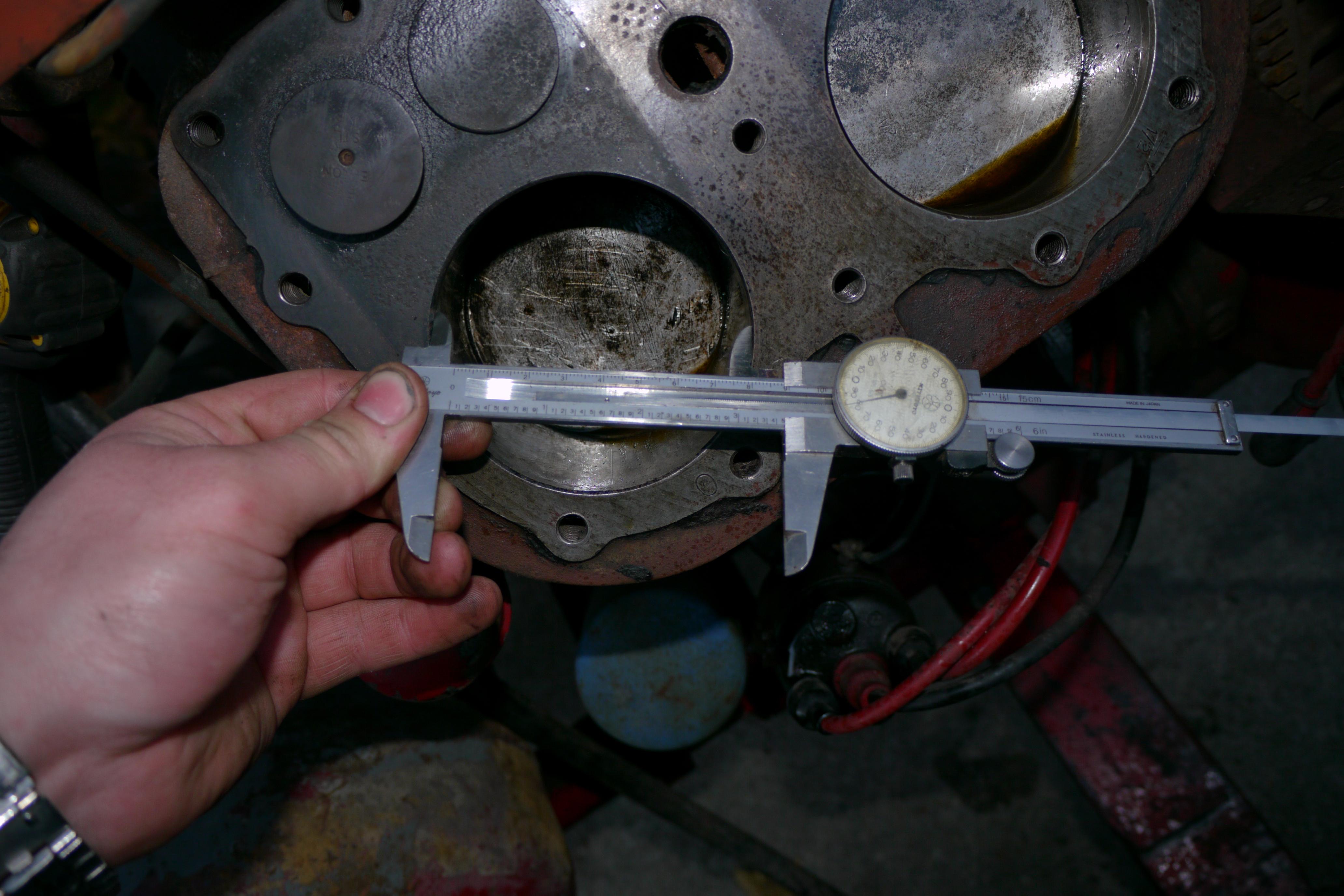
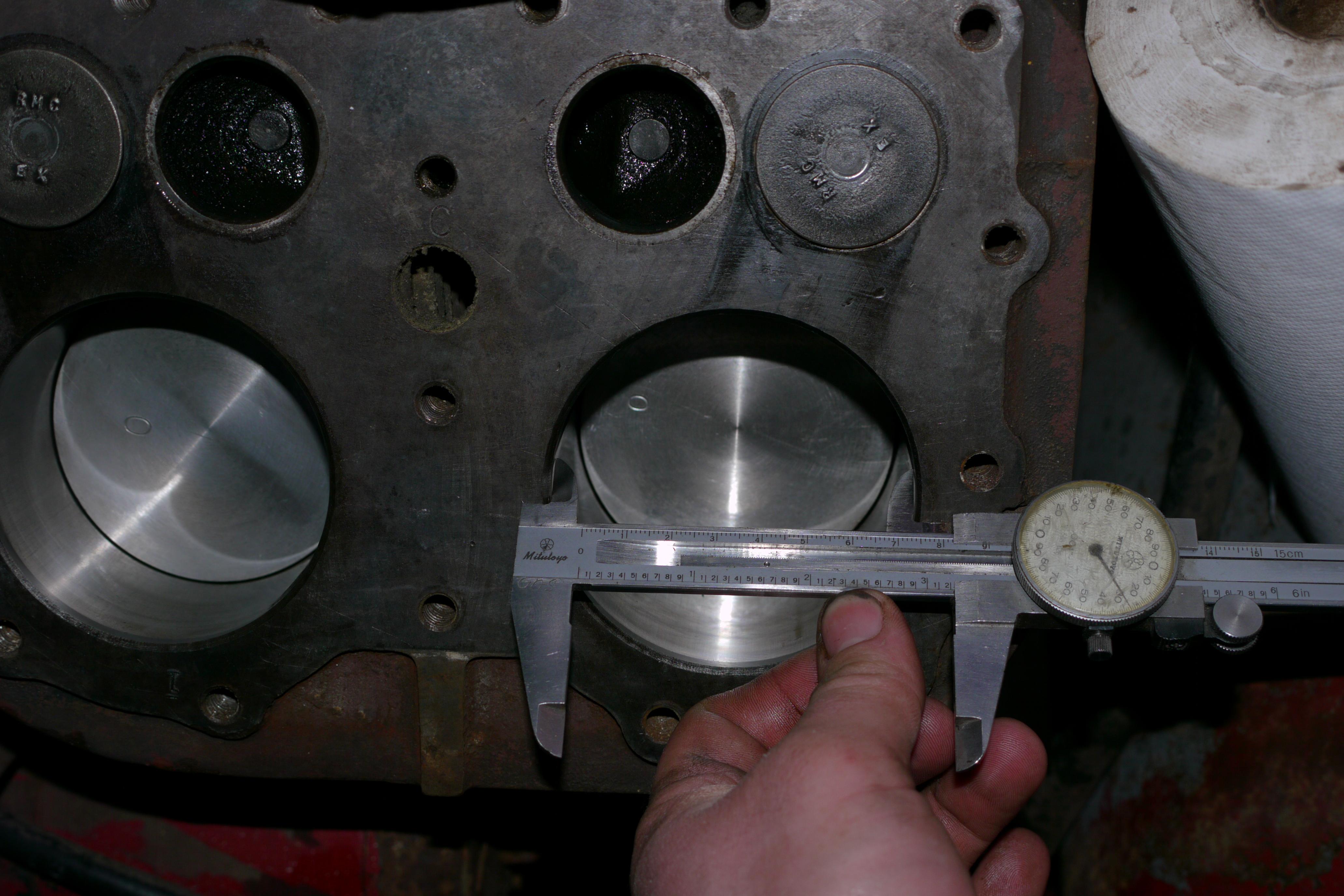
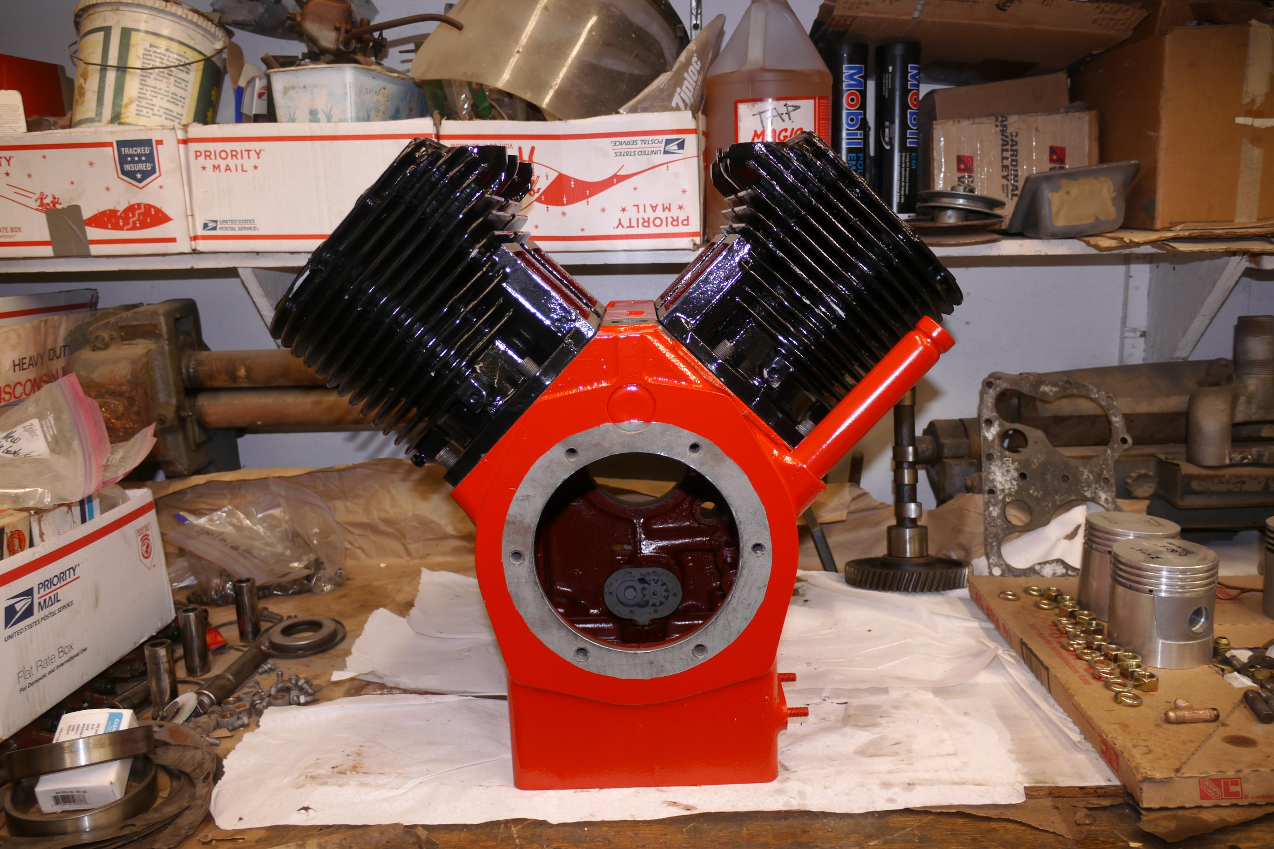
Because there is little to no information online about Schramm compressors, I was surprised to see that the engine side of the compressor had 3-1/2″ pistons, while the compressor side was fit with 3-1/4″ pistons. I eventually discovered that the reason the compressor side of the engine had smaller pistons, and thus less displacement, was to give the engine an effective advantage over the power absorbing air compressor.
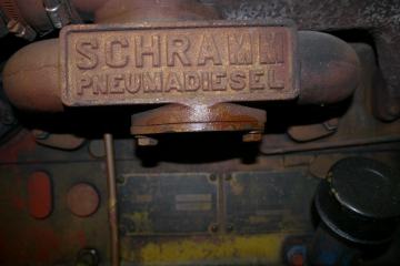
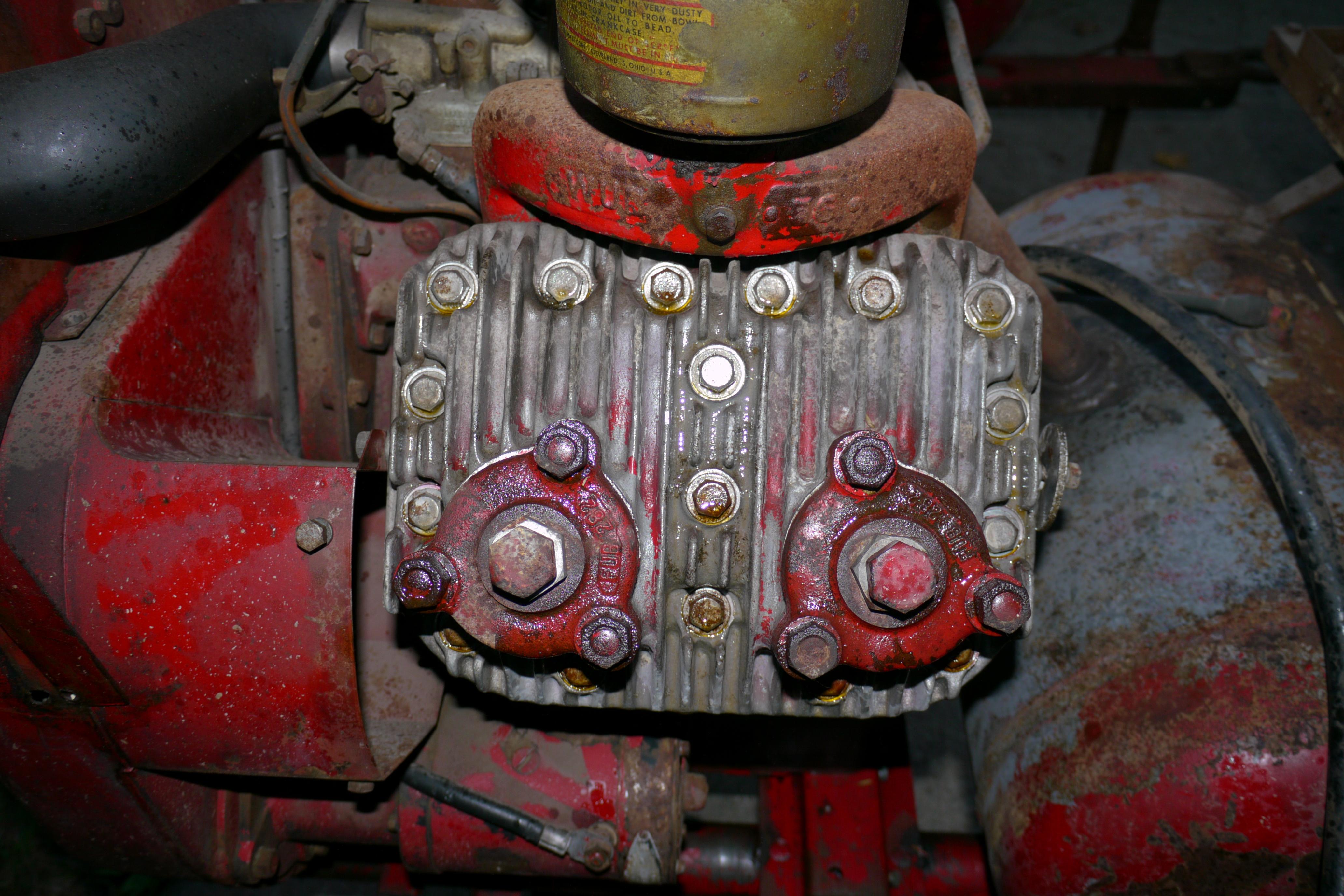
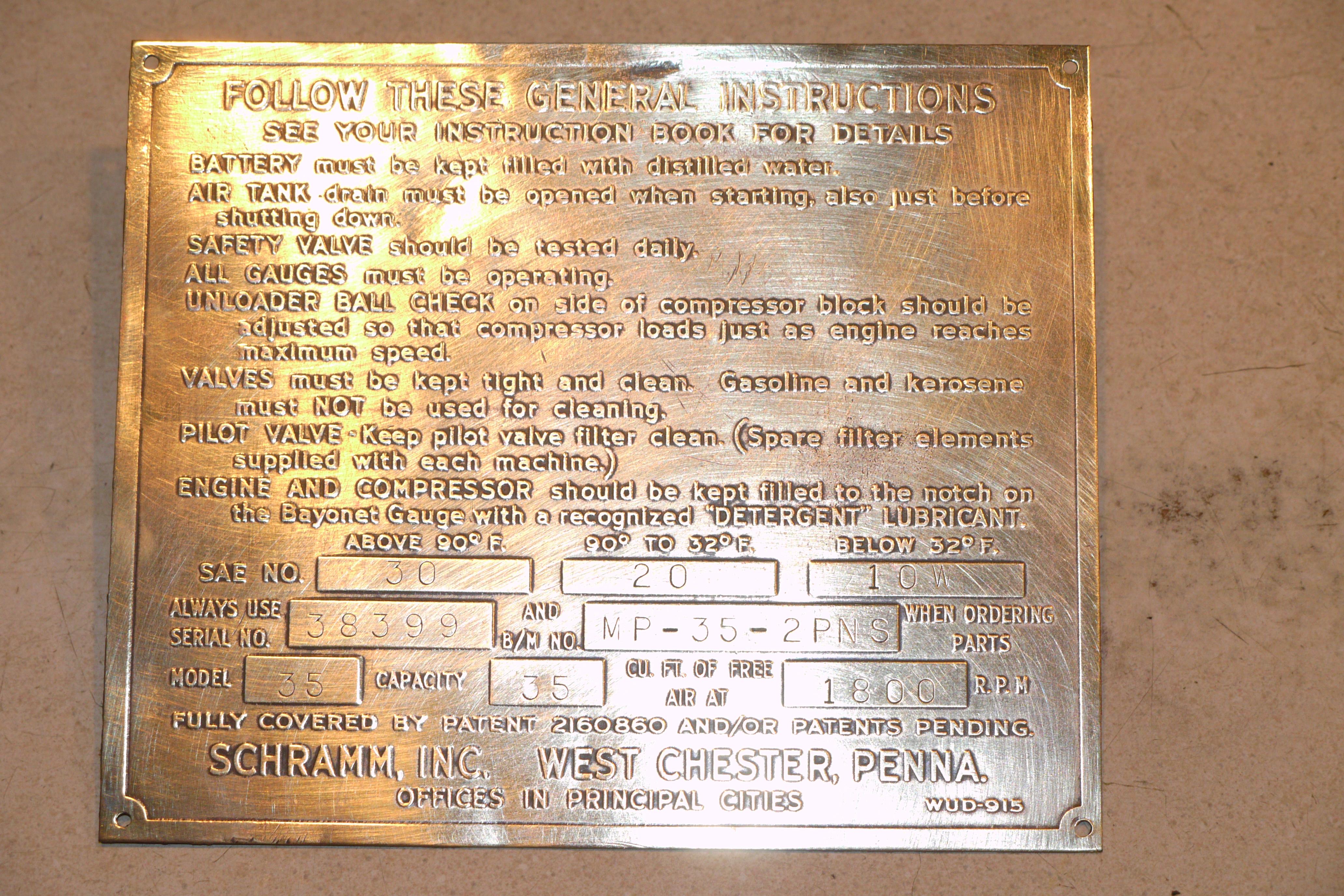
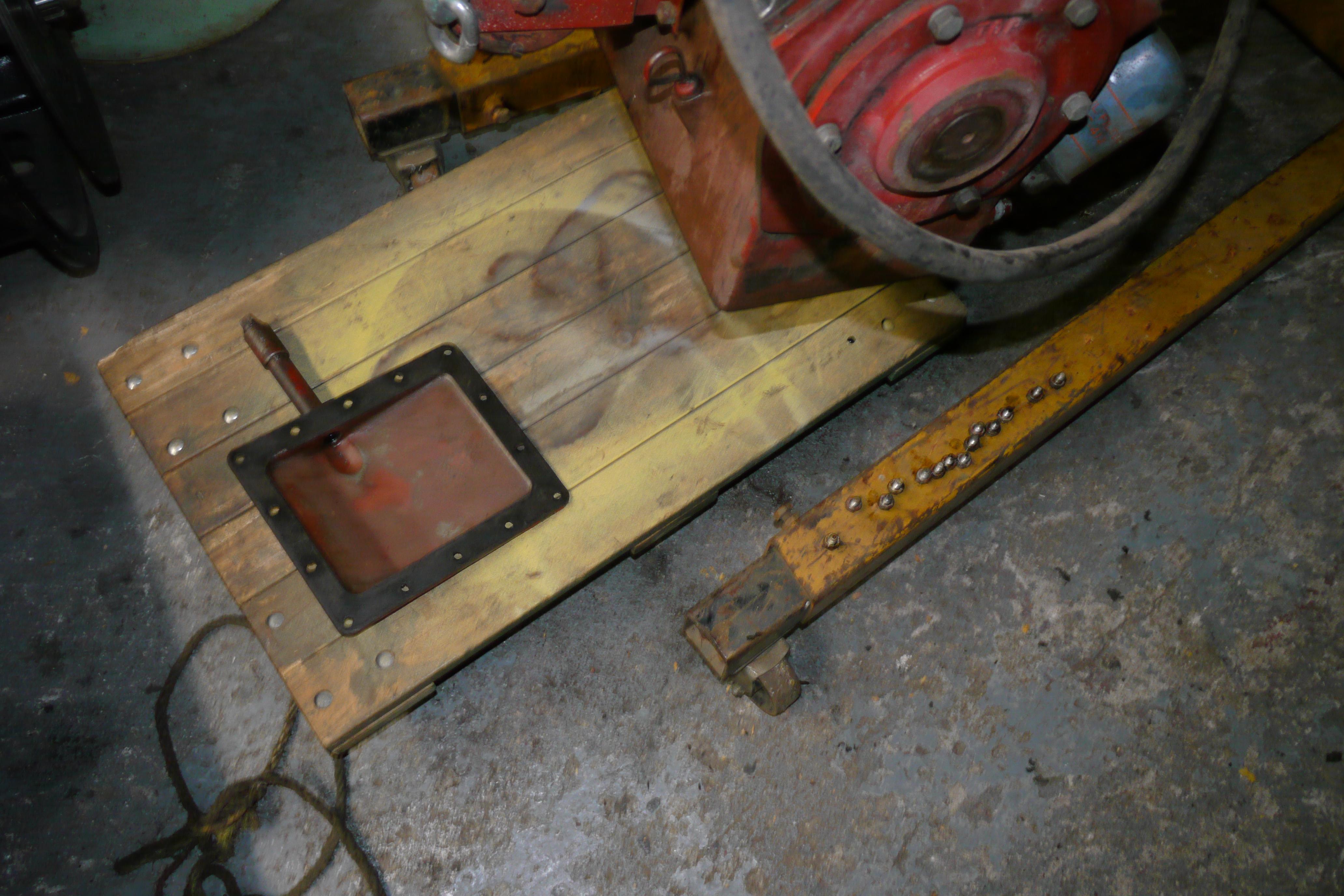
Excited to see the compressor side of the engine in such nice shape, I went about cleaning up the brass information tag that was fitted to the side of the Schramm compressor housing. With a little Brasso and a worn scotch-brite sponge I was able to clean all of the corrosion off of the tag.
Design Decisions
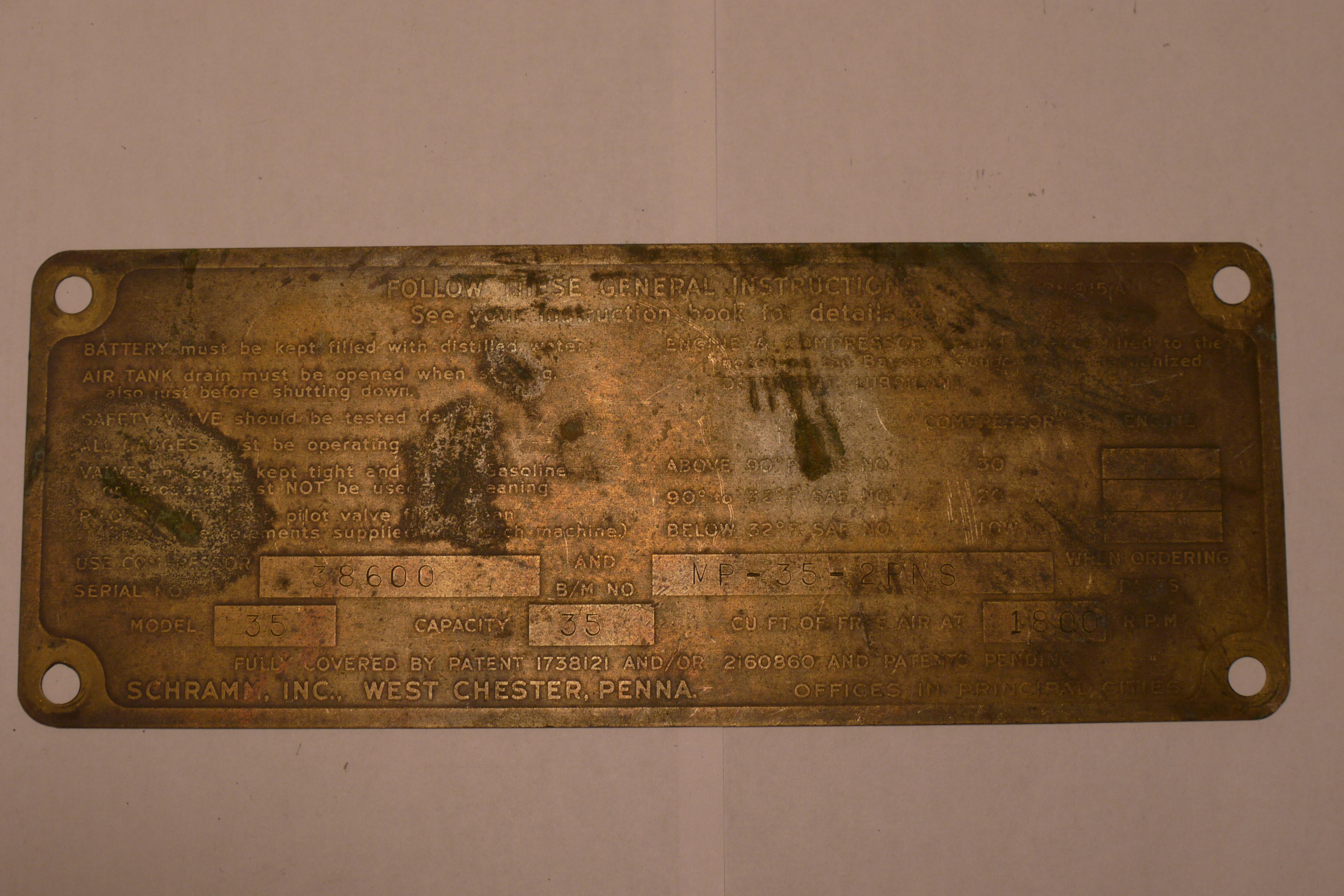
Disappointed that the other compressor did not have an identification tag, I contacted Gail, and sure enough in a weeks time the brass identification tag for the other compressor came in the mail. Thank you Gail!
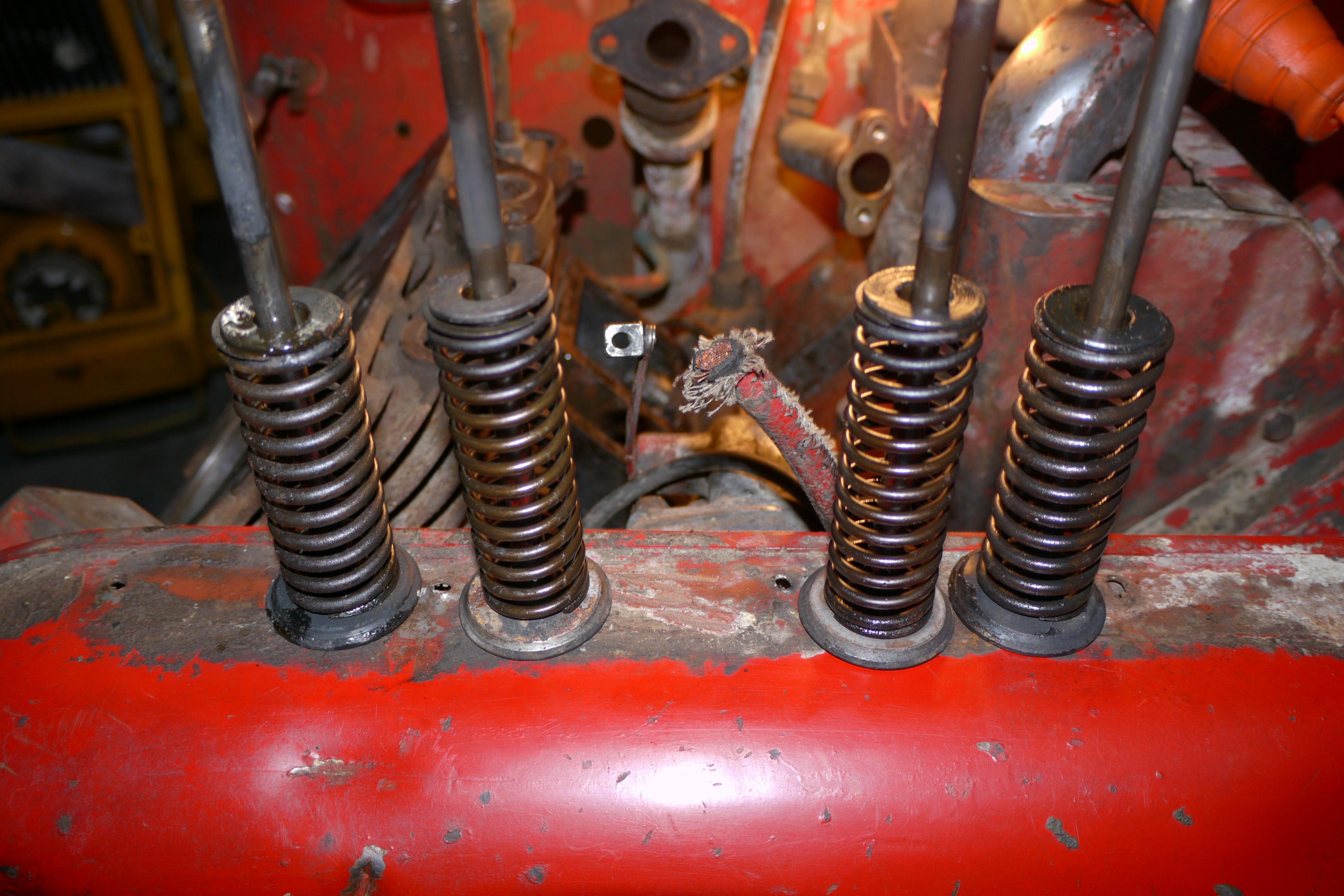
With both compressors turning 360*, I decided that I was going to restore and rebuild the 1952 Schramm Pneumapower 35 for my truck project, and the 1950 I would restore at a later time as a portable compressor on its original trailer. With the 1952 in mind for my truck project, I decided to dig a little into the 1950 to see how well it ran and compressed air. Restoring and rebuilding vintage engines and machinery is certainly not cheap, and I wanted to be absolutely sure that this compressor was right for the job. Turning the 1950 over by hand, you could feel that the engine had very low compression. Judging by how dirty and gummy the inside of the engine was on the first day, I decided that I would have to pull the valves and clean them up good before running the engine. In order to remove the valves from a Wisconsin V4 engine, you have to first remove the intake and exhaust manifolds. Once the manifolds are out of the way, you can access the valve covers. Before pulling the valve covers it is imperative that all of the dirt, grease/grime and concrete dust from the cavity of the engine is removed. Once the vee of the engine was clean I was able to remove the valve covers and remove the valves from the engine.
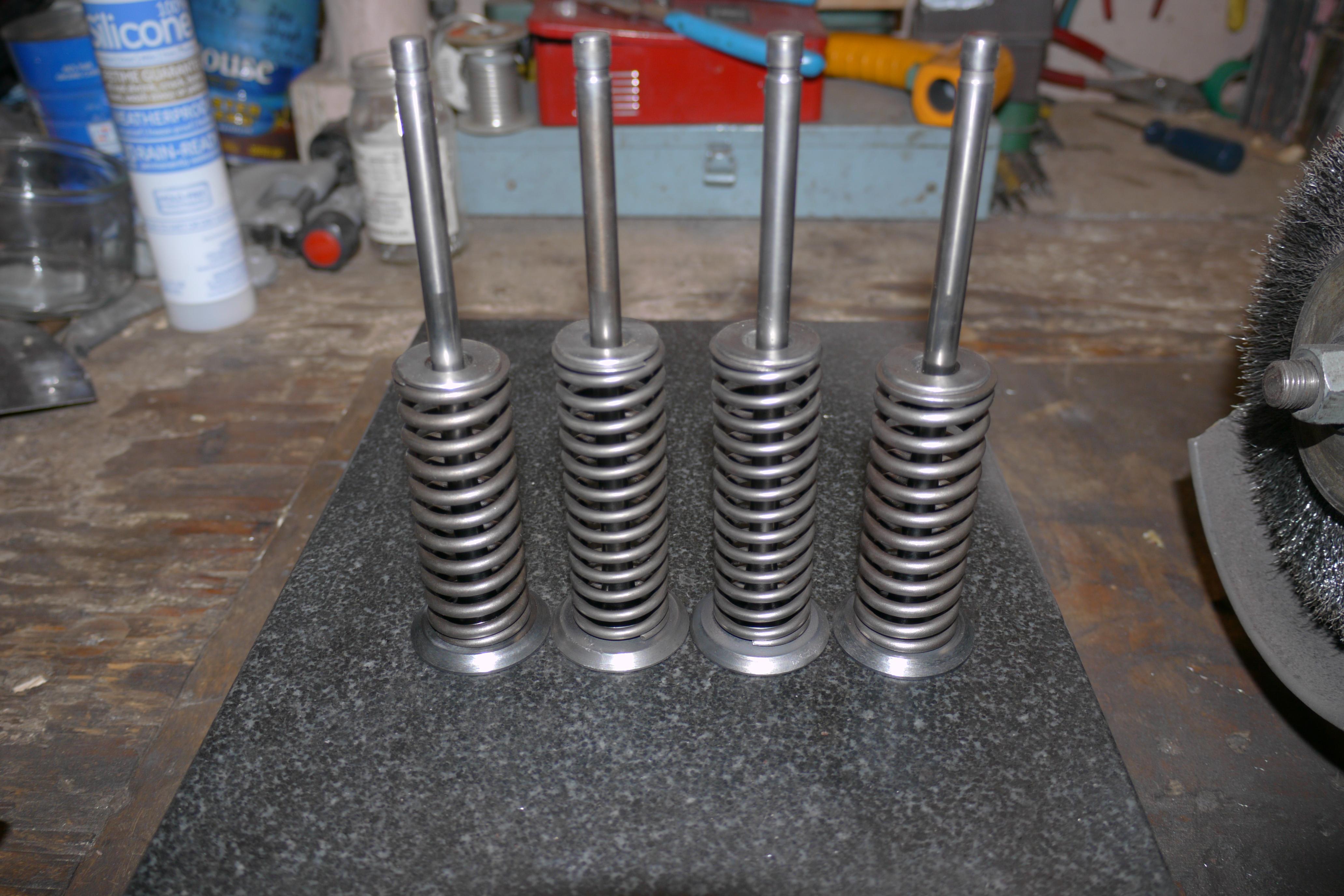
All four valves in the engine side of the compressor were sticky and had to be pulled out of the engine. Once removed, I cleaned the dried up fuel varnish from the valve stems, reamed the valve guides with a 5/16″ reamer, and lapped the valves to their corresponding seats with lapping compound.
One of the intake valve seats was chipped and excessively worn. Worn intake valve seats and guides are an indication that the engine was run without adequate air filtration. I lapped the intake valves as best as possible without cutting the valve seat and grinding the valve. When I put the valve train back together I had significant leakage around the valve seat. I was not happy with it, but decided it was worth putting it back together to see if it would run. The worst case scenario, the compression of the engine would blow the air fuel mixture out of the throat of the carburetor.
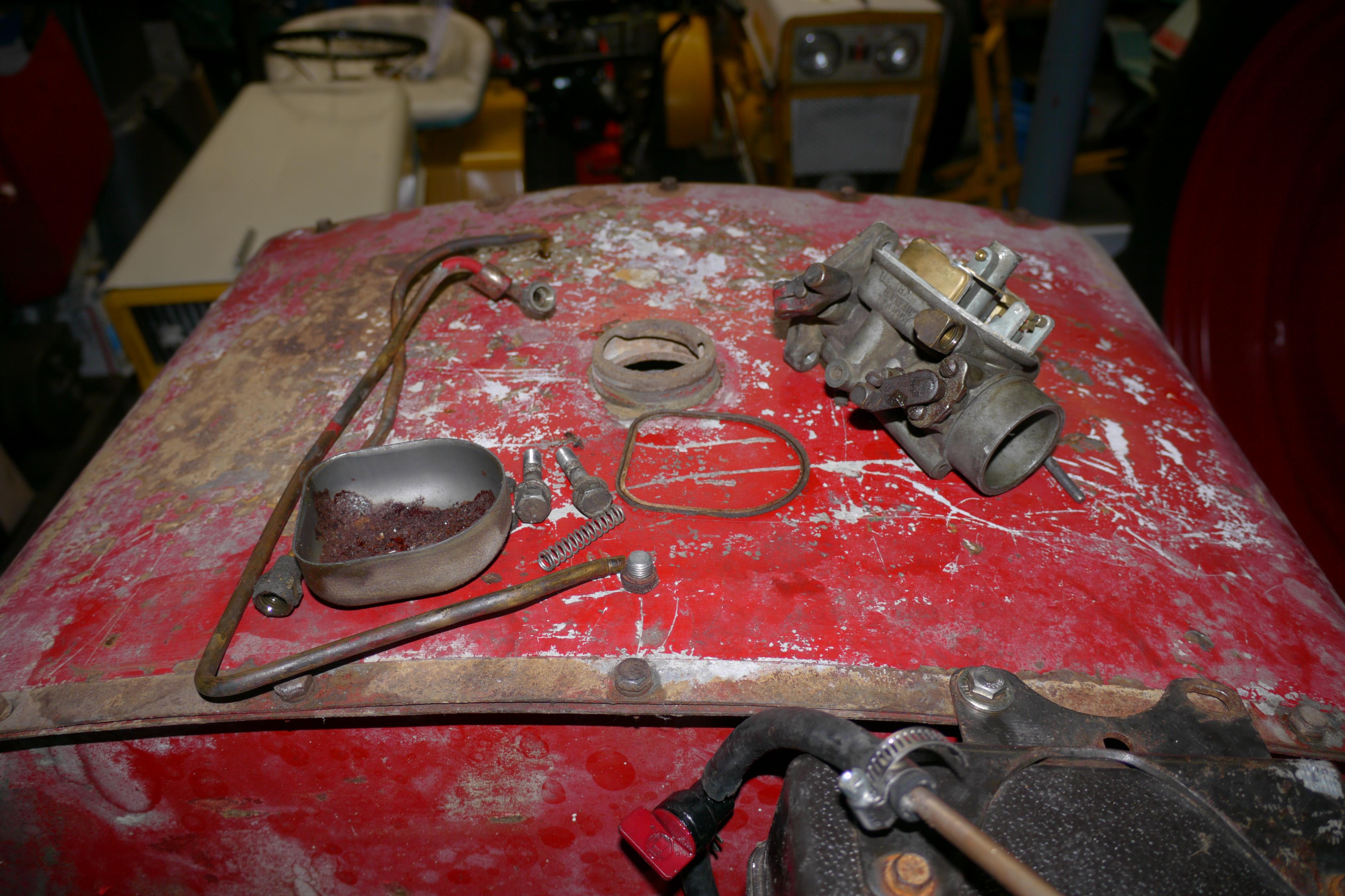
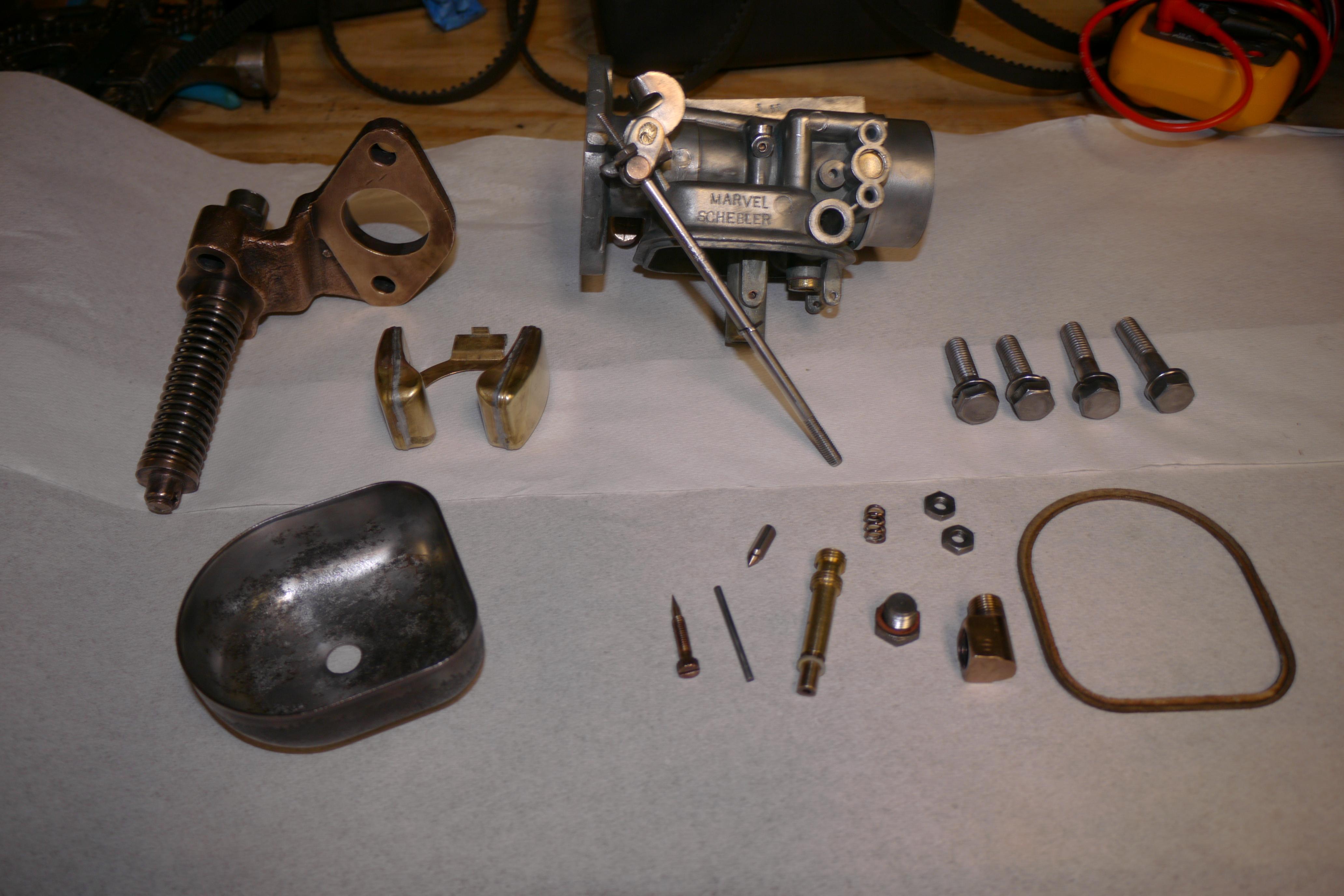
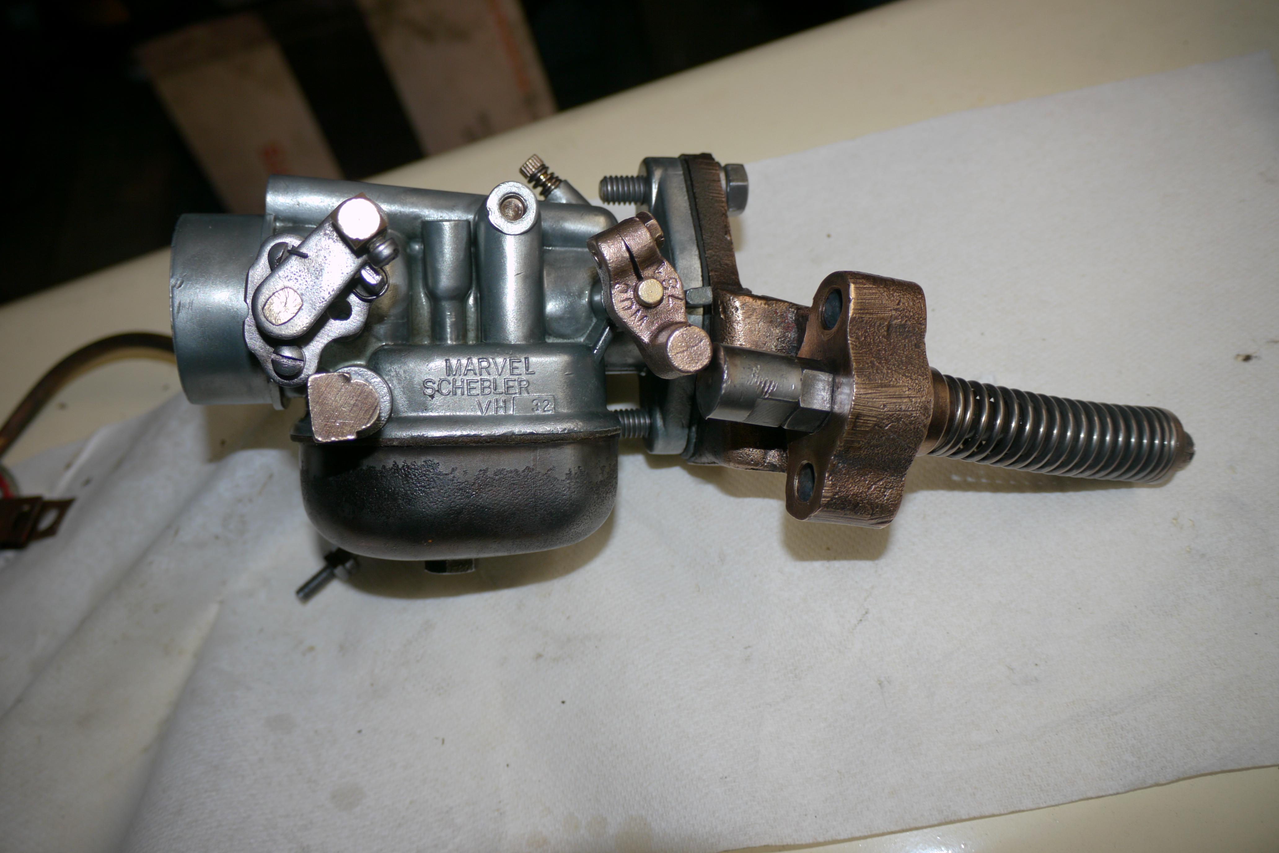
I fit the intake and exhaust manifolds back to the engine with new gaskets, and started working on the carburetor. The Marvel Schebler VH-32 carburetor was full of corrosion and oxidation. It was in pretty bad shape overall. I submerged the carburetor in a 50/50 solution of Simple Green and distilled water in my ultrasonic cleaner for an hour and it cleaned up well. I blew out all of the passages with compressed air, set the brass float and proceeded to assemble the carburetor.
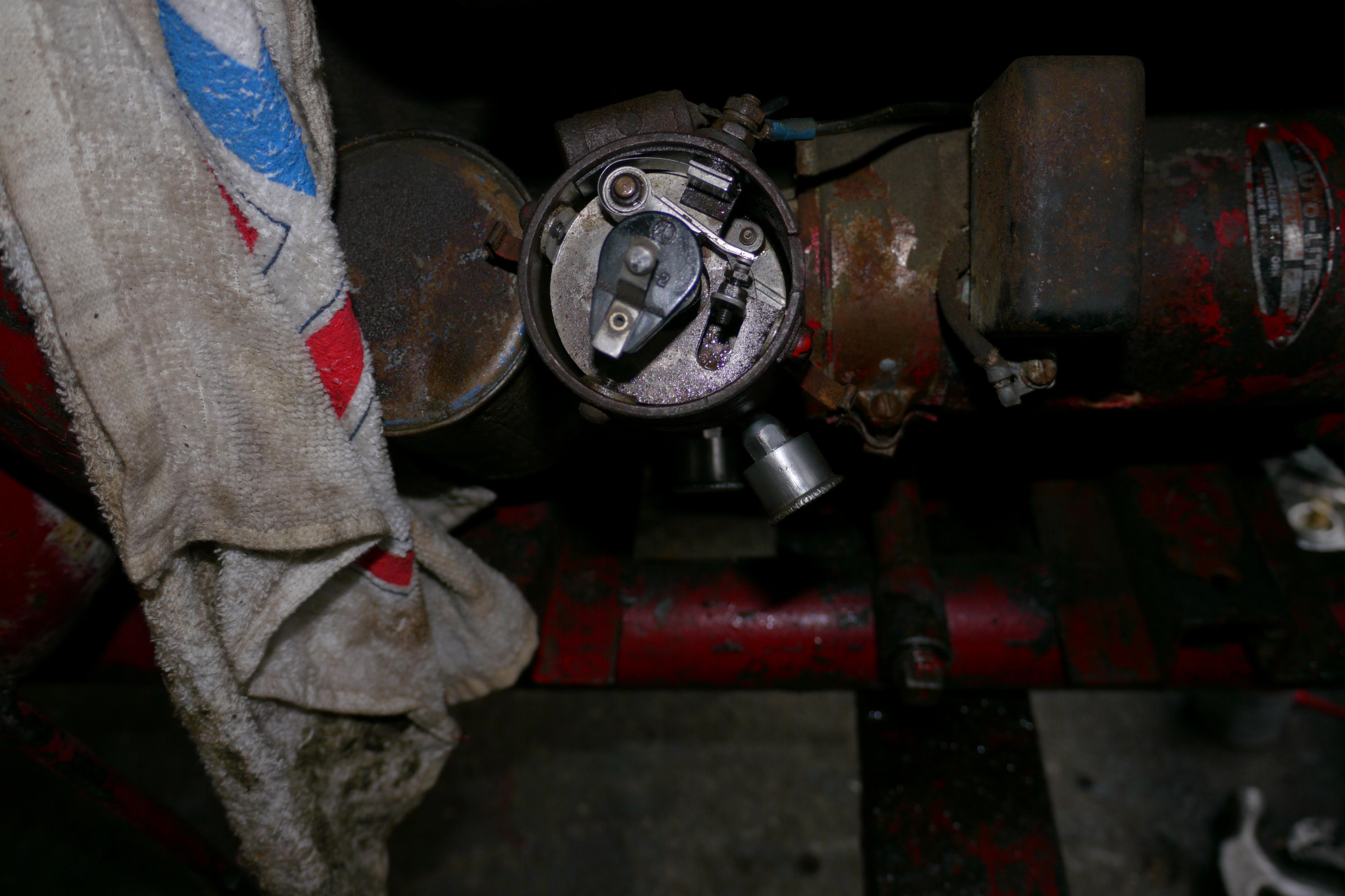
With fuel and compression straightened out, I just had to address the lack of ignition. I pulled the cap off of the distributor, filled the points with an emery board, gapped the points at 0.018″ and fit the cap back on.
With fuel, compression and ignition, all I had to do was clean the old oil out of the engine and check that the oil pump was not seized up. As you can see this engine was very dirty inside. It took a while to wash out all of the old oil from the engine.
After I filled the crankcase with fresh oil, I gave it a whirl. It took some time to get the engine running, as the distributor was not timed correctly. The distributor was set too far retarded, and would cause the engine to backfire. I was able to get the engine running and the compressor running satisfactorily. I was actually surprised how fast the compressor built air in the integral air tank. Getting this compressor up and running taught me a few things about what was necessary for the other unit. I noted the engines lack of power, (mostly due to poor valve seats and low compression in one cylinder), and decided that if I wanted a high performance compressor I would have to address the engine’s overall compression ratio, smooth and polish the rough integral intake and exhaust castings, add magneto ignition for hotter spark and better hand crank start capabilities, and go through all of the pilot and relay valves in the compressor with a fine tooth comb. The air valves on this unit were very touchy and had to be set just right for perfect operation. The valves themselves are pitted and corroded from moisture and age, and were not working like they should.
Despite the 1950 being in overall sad shape, it was still quite an impressive machine. I decided that it was exactly what I wanted and needed for my truck project. I rolled the 1950 back into the storage shed and started working on the 1952.
From this point forward this post will cover the complete disassembly, cleaning, inspection and rebuilding of the 1952 Schramm Pneumapower 35 compressor.
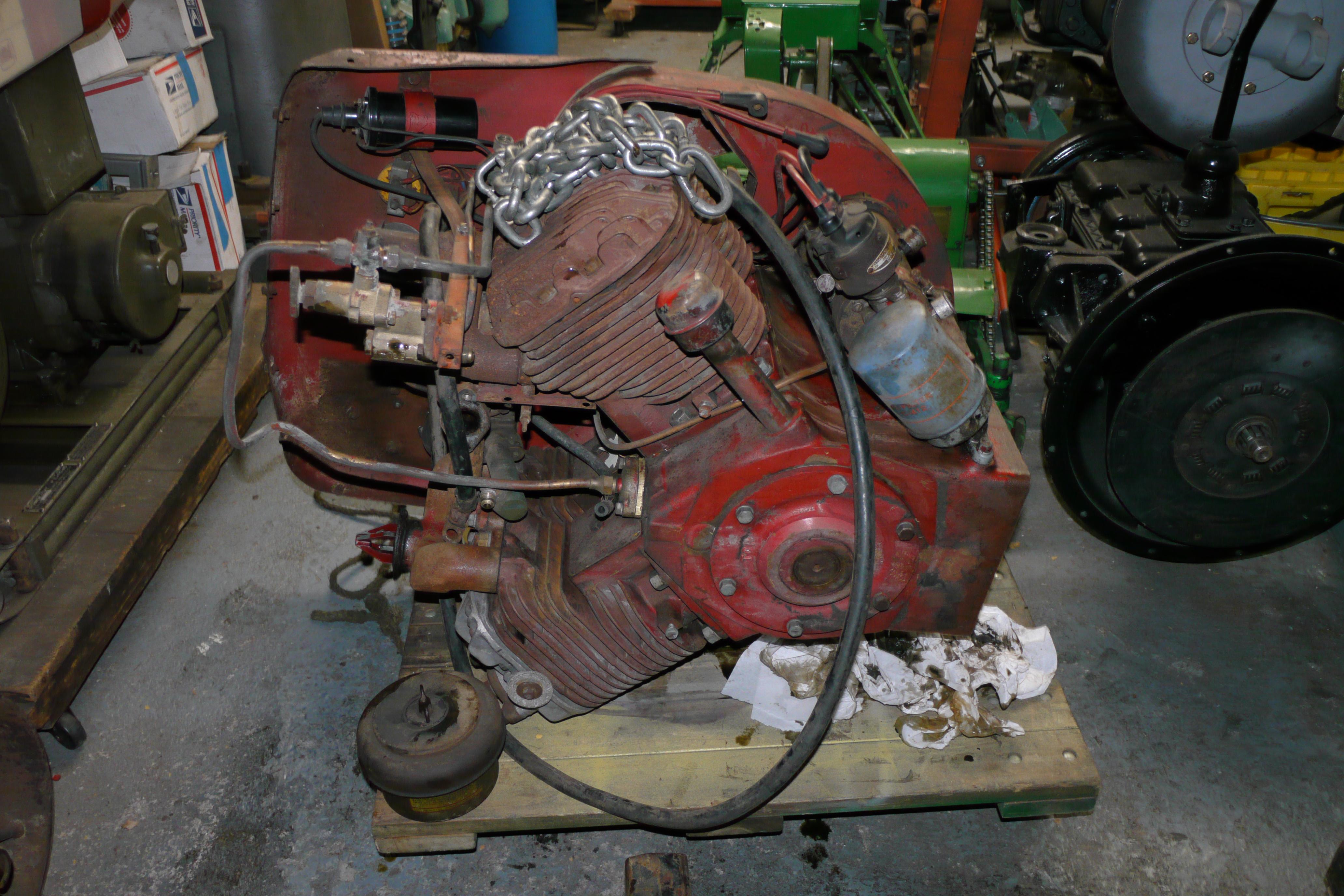
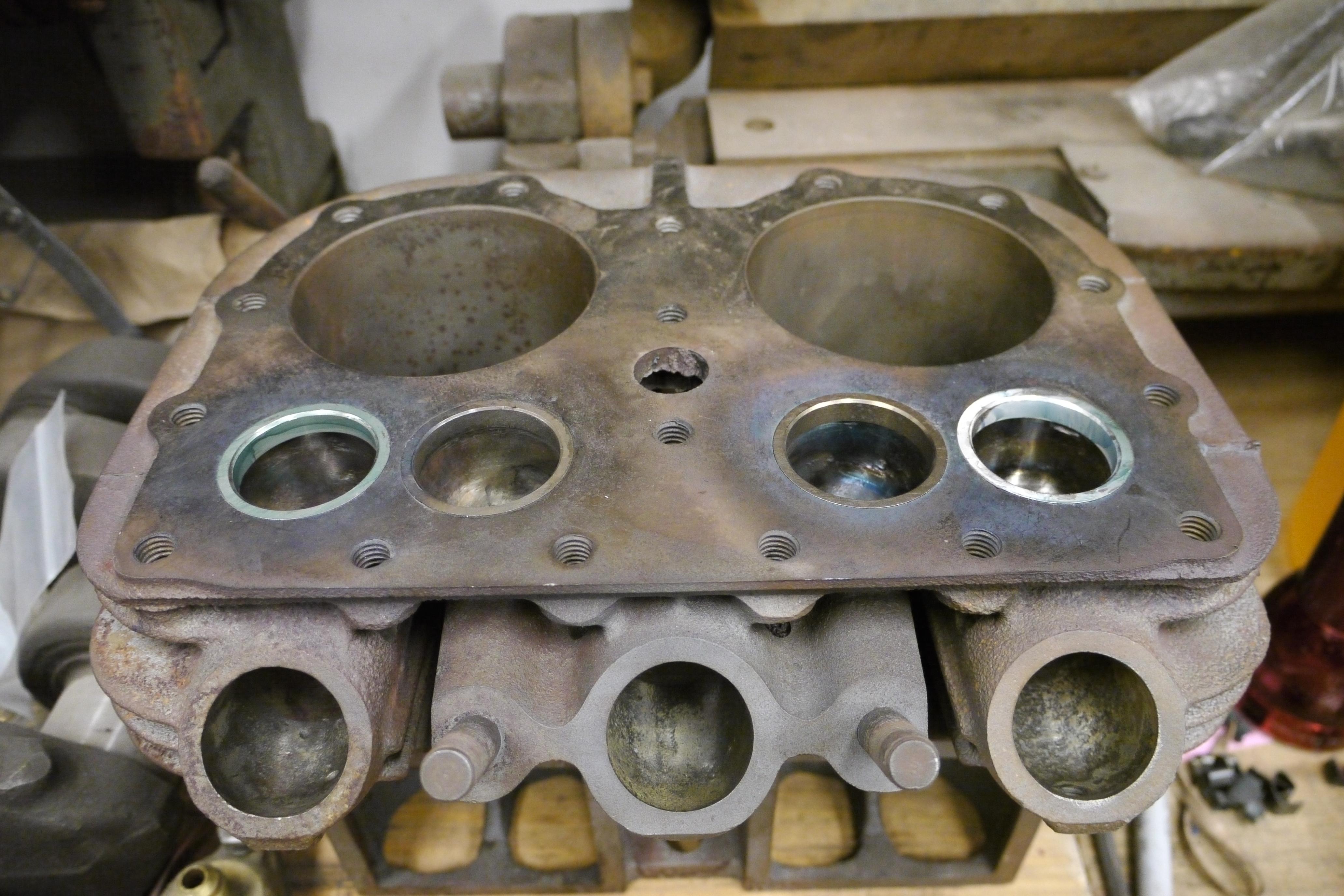
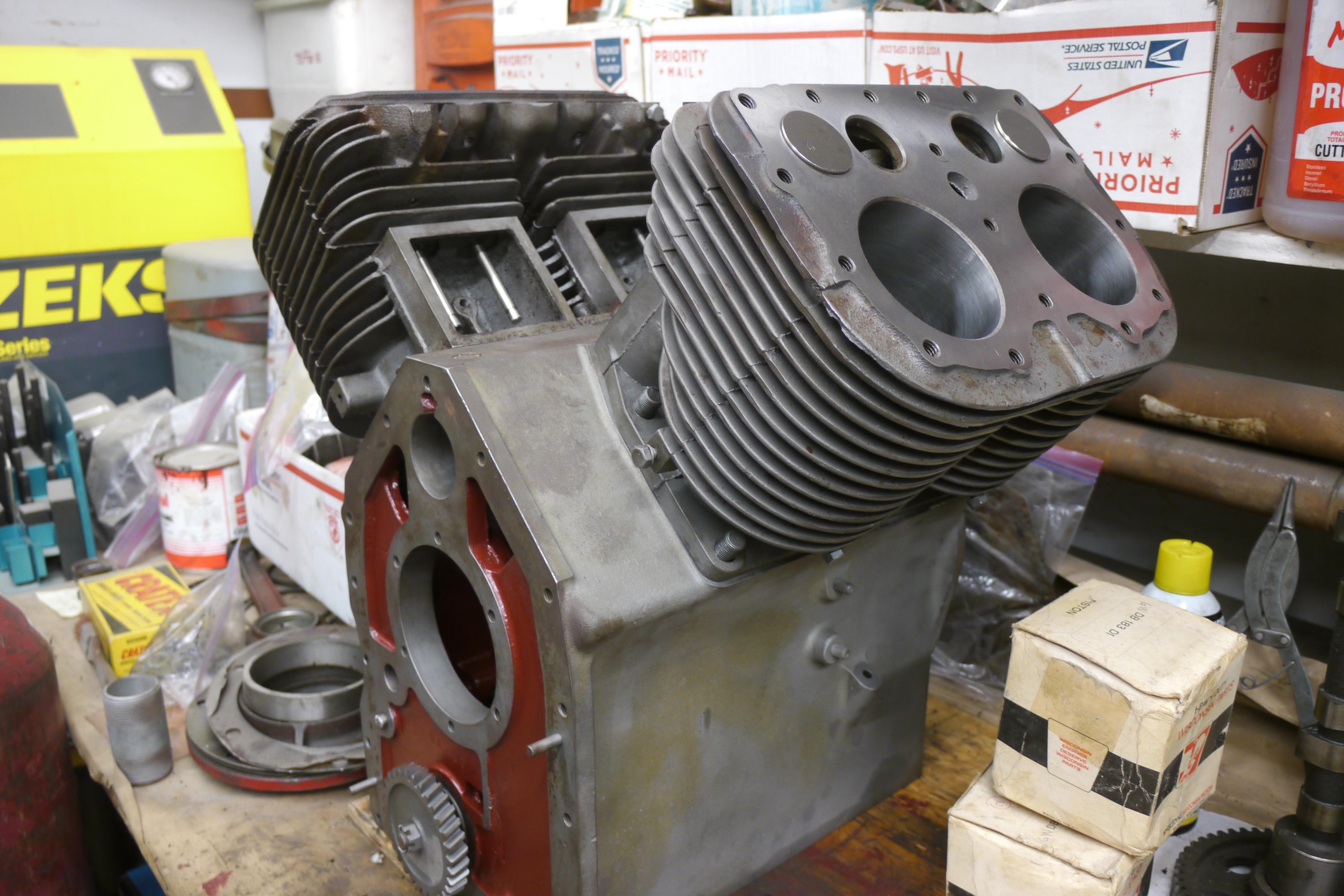
The base engine of this compressor is the Wisconsin VP4. The VP4 is normally a 154 cubic inch, 31 horsepower flat head four cylinder engine with 3-1/2″ bore and 4″ stroke. Its dry weight is 410lbs. It produces 93 lb/ft torque at 1500RPM and develops its peak horsepower at 2200RPM. Schramm dropped the governed operating speed of this engine to just 1800RPM, and cut the effecting engine in half resulting in a power plant rated 14.5 horsepower at 1800RPM generating a peak torque of 44 lb/ft torque at 1500RPM. A rule of thumb for electric compressors is that 1 horsepower equals 4 cubic feet a minute of air volume. For gasoline engines this metric is reduced to 3 cubic feet a minute of air volume per horsepower. With a rating of 14.5 horsepower, this engine is theoretically capable of turning a 43.5cfm capacity compressor. Schramm rated these compressors at 35cfm, which is quite a large compressor by any standard. To give the engine a mechanical advantage, Schramm removed one cylinder jug and fit a cylinder jug from a VM4 engine (3-1/4″ bore) to the VP4 engine. This combination gave the engine ample power to run the power absorbing air compressor. It is clear that Schramm specifically used this engine because it shares a lot of similar engine parts with the smaller bore VM4 engine. The biggest similarity between the VM4 and VP4 is the use of an alternate firing single plane crankshaft. Modifying a V4 engine with a single plane crankshaft is much easier than modifying a V4 engine with a cross-plane crankshaft. This allowed Schramm to simply unbolt one cylinder jug and head and fit a smaller bore cylinder jug in its place without any adapters or custom parts. Schramm literally turned one half of the engine into an air compressor by designing a custom camshaft (so one half of the engine can two-cycle while the other four-cycles), a custom cylinder head with discharge valves, and by employing their custom two part valve lifters. Using this type engine greatly simplifies the conversion, but it comes at a cost. The firing order of these engines is 1-3-2-4, where 1 and 3 are power strokes and 2 and 4 are compressor strokes. As a result the compressor doesn’t run very smooth. It would have been better if they used a VG4D engine to start with, which had a cross-plane crankshaft and could have been setup so that the engine fired between every stroke of the compressor. It is evident why Schramm built this engine the way they did. They needed to make the compressor half of the engine two-cycle while the engine half of the engine four-cycled. The engineers at Schramm had a custom camshaft made up, as well as a set of custom brass valve guides for a custom set of hollow valve lifters. Schramm used the crankcase of the engine as an unloader valve. When 125 psi of air pressure was built in the tank, the air pressure would push a spring off its seat in the pilot valve, which would send high pressure air into the crankcase via two 1/16” copper air lines. These lines supplied air into the custom Schramm brass valve guides. Schramm used a two piece lifter fitted with scraper rings and sealing o-rings. When 125 psi of pressure is met, the air forces the upper half of the lifter to push upwards floating the “exhaust” valves in the compressor. The cylinder jug of the compressor half of the engine only uses traditional Wisconsin exhaust valves. Because the compressor operates in a two-cycle fashion, the intake valve guides are plugged. Air is sucked through an air-maze air cleaner into the compressor by conventional Wisconsin exhaust valves. Air is compressed and discharged through overhead Schramm disc type discharge valves mounted above the cylinders. The pressurized air is then sent through the typical air intake ports to the horizontal receiver (air tank). The setup is for the most part simple, but includes a lot of complicated valves in order to make it work. The aforementioned internal unloader valve works in unison with an air cylinder which fills with the same pressurized air from the pilot valve, to automatically idle the engine back down when working pressure is met. It will take a lot of fine tuning to get this compressor running and working like it should. If the unloader valves operate after the idle cylinder extends the engine will run out of power and stall out. If the unloader valves kick in before the air cylinder idles the engine back down it could over-speed. So four valves need to work in complete unison with each other for perfect operation. When setup correctly, the compressor will throttle up by itself and idle back down by itself based on how much air is called for. Based on the volume output of this compressor it will be able to charge the eighty gallon on board air tank in just under three minutes. Once rebuilt it will be able to provide a lifetime supply of air for all of my needs both truck and tool related.
Restoration Process
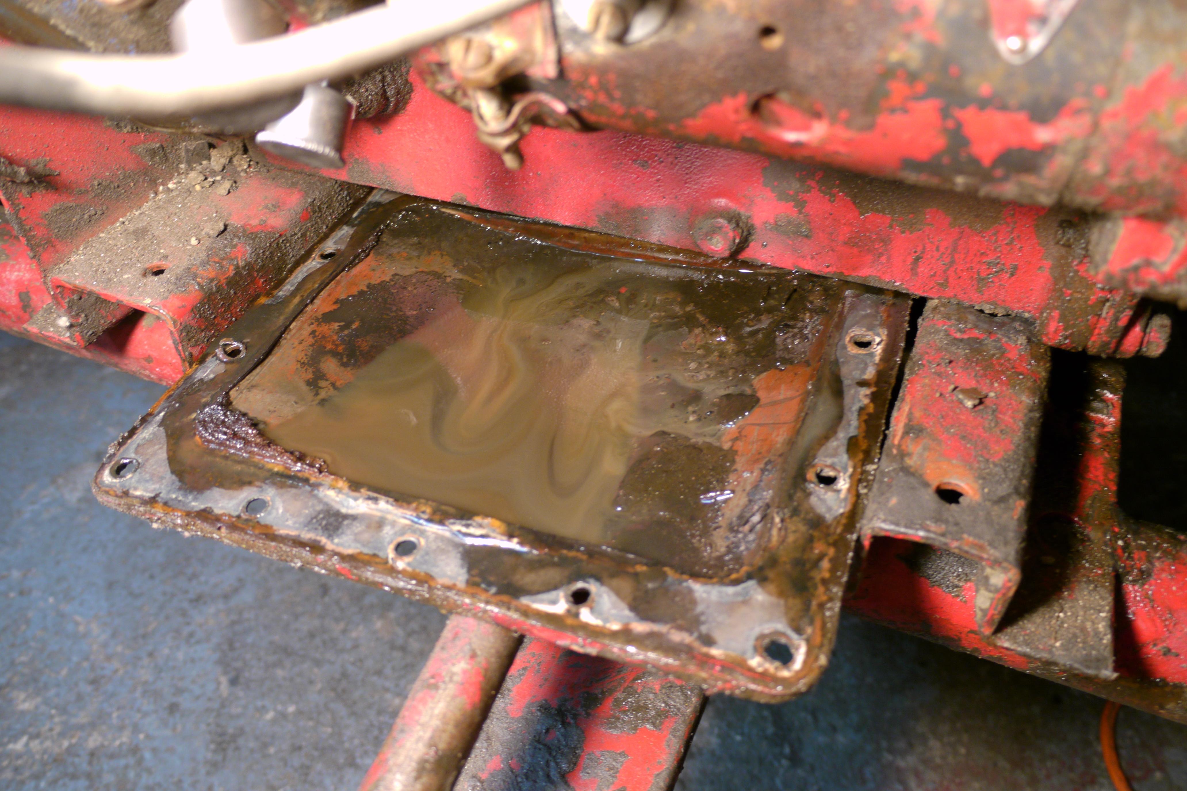
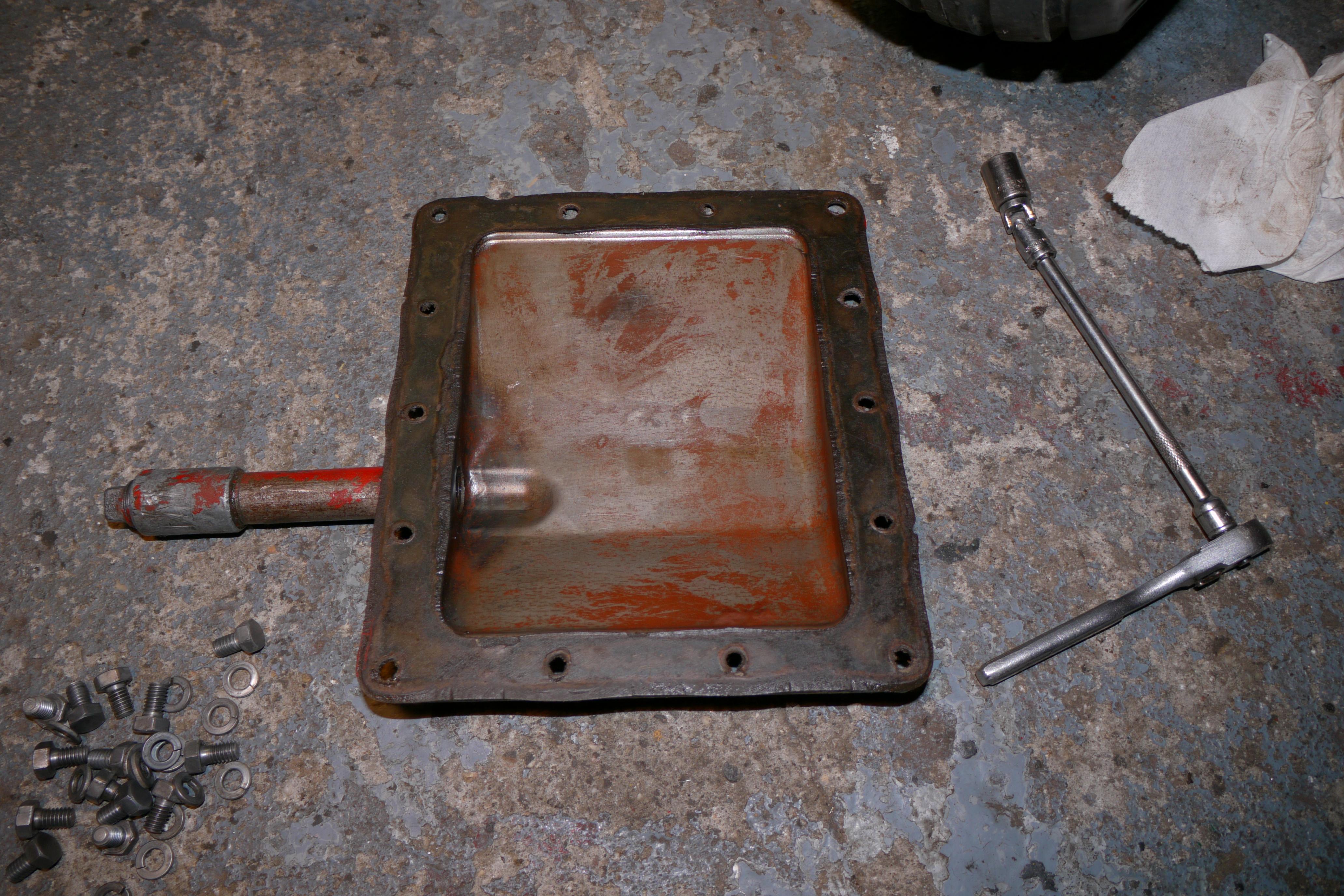
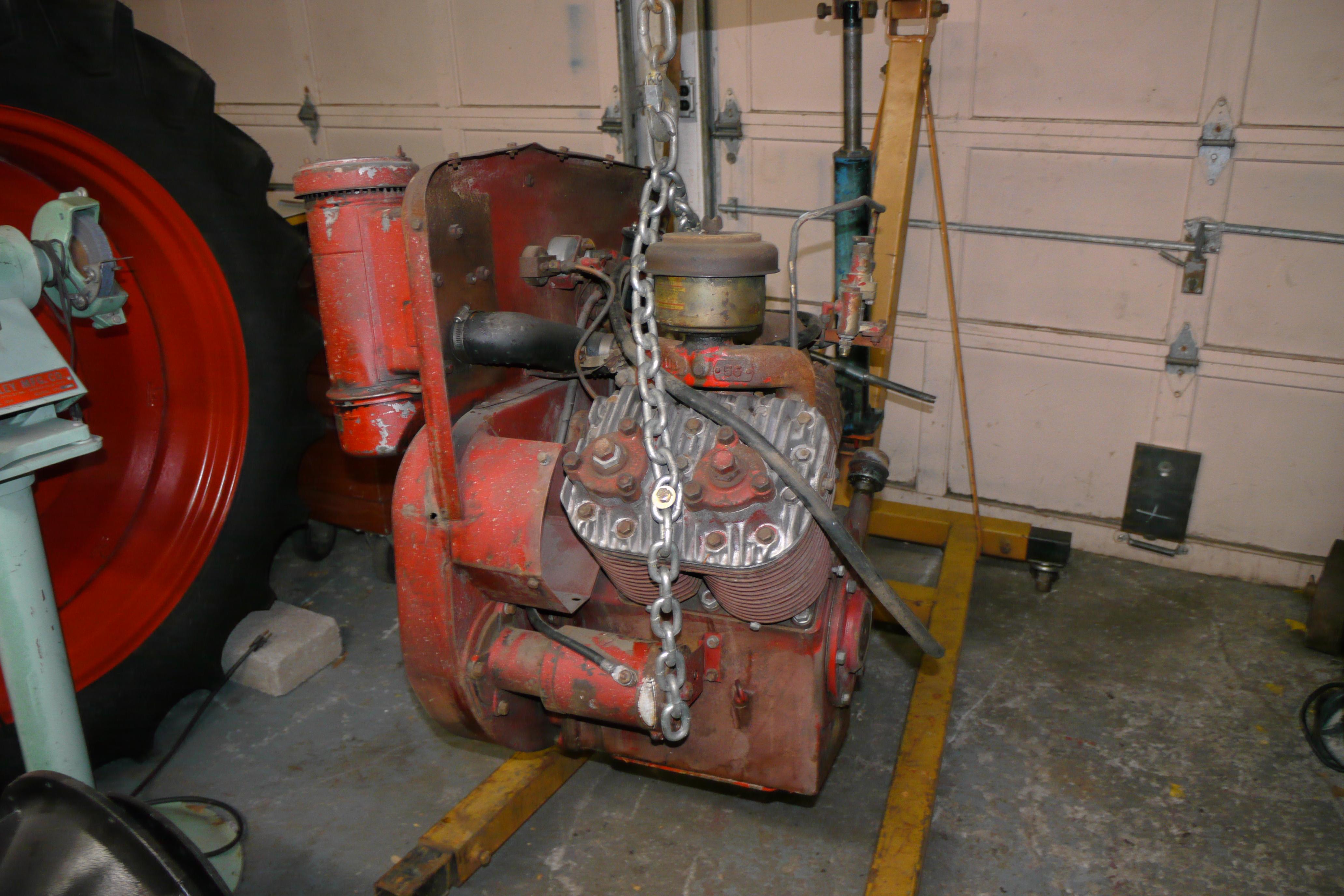
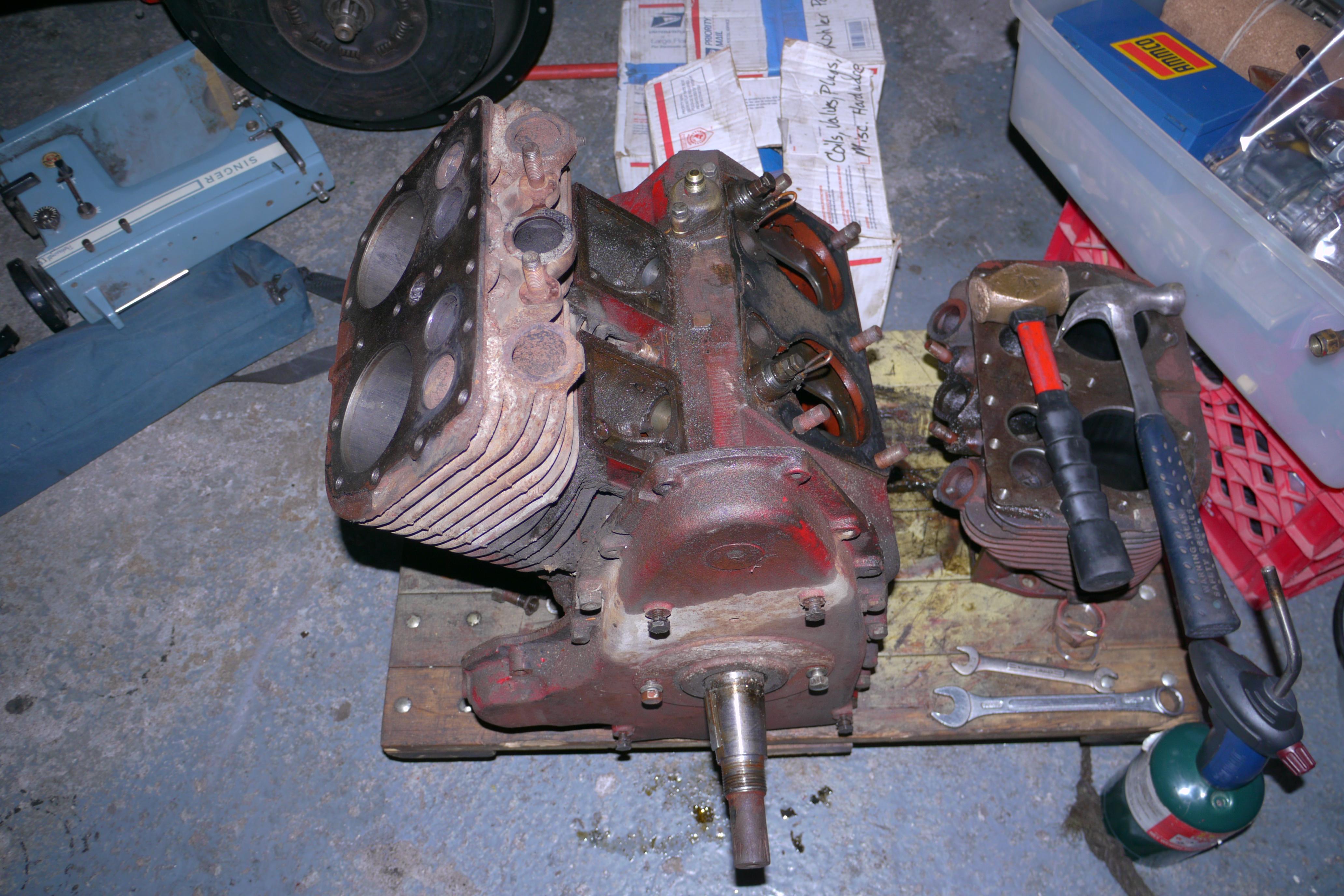
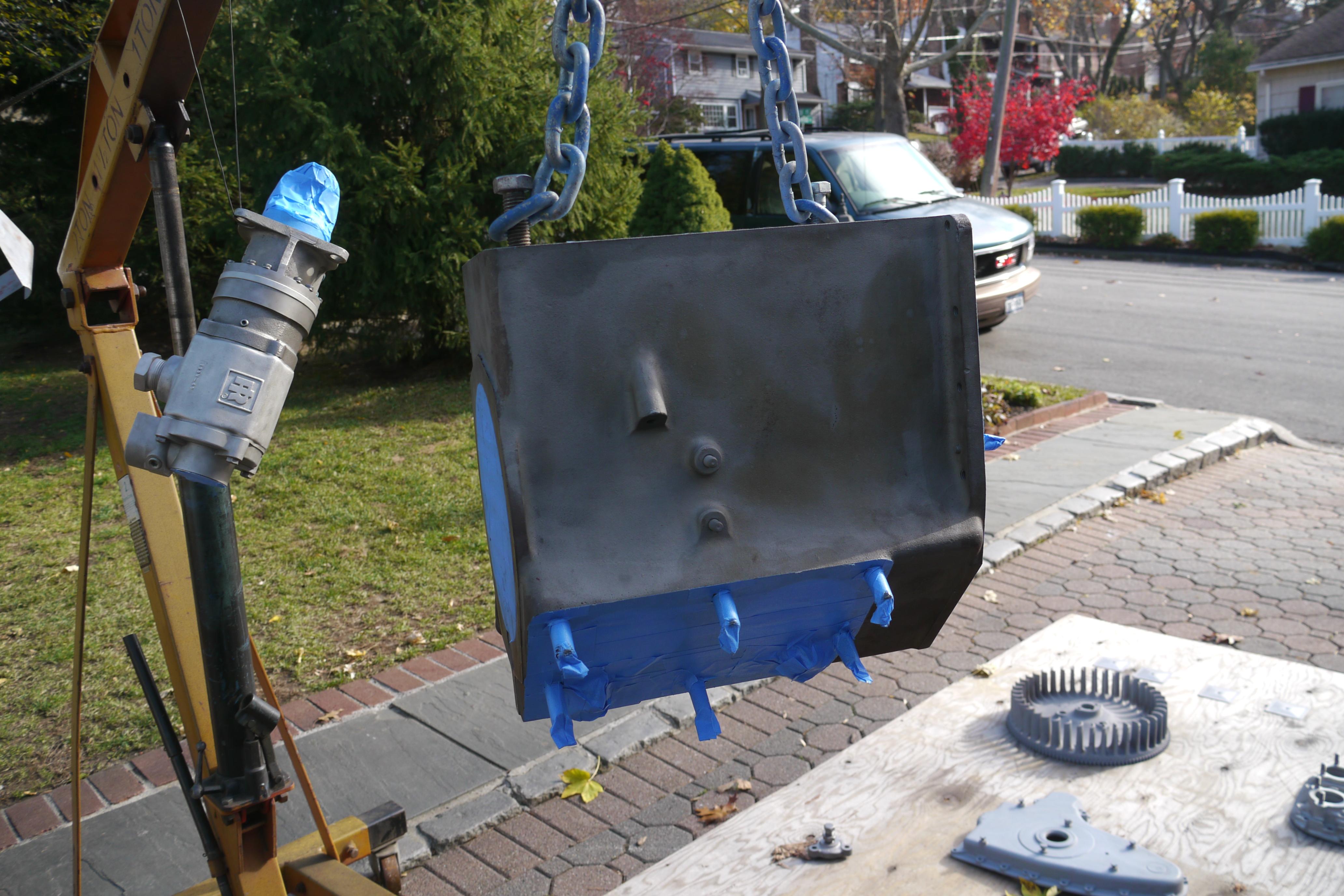
As mentioned above, both of my Schramm Pneumapower compressors were dry-seized from sitting unused for years. The first step was to remove the engine from its dolly so that it could be cleaned and disassembled. I removed the oil pan so that I could clean all of the sludge and greasy oil from the oil pan and the lower half of the engine. Nine times out of ten the stainless steel check balls in the oil pump are sticky with varnish after sitting for a long period of time. It is one of the reasons that I never run a newly acquired engine without pulling the oil pan. You never know what you are going to find! Usually you find a quarter inch to a half inch of grease slimy sludge in the oil pan, but this time I found something extra! I found a half empty bottle of prescription pills. They must have fell down the oil breather tube into the oil pan of the engine. In hindsight I should have taken a picture of that!
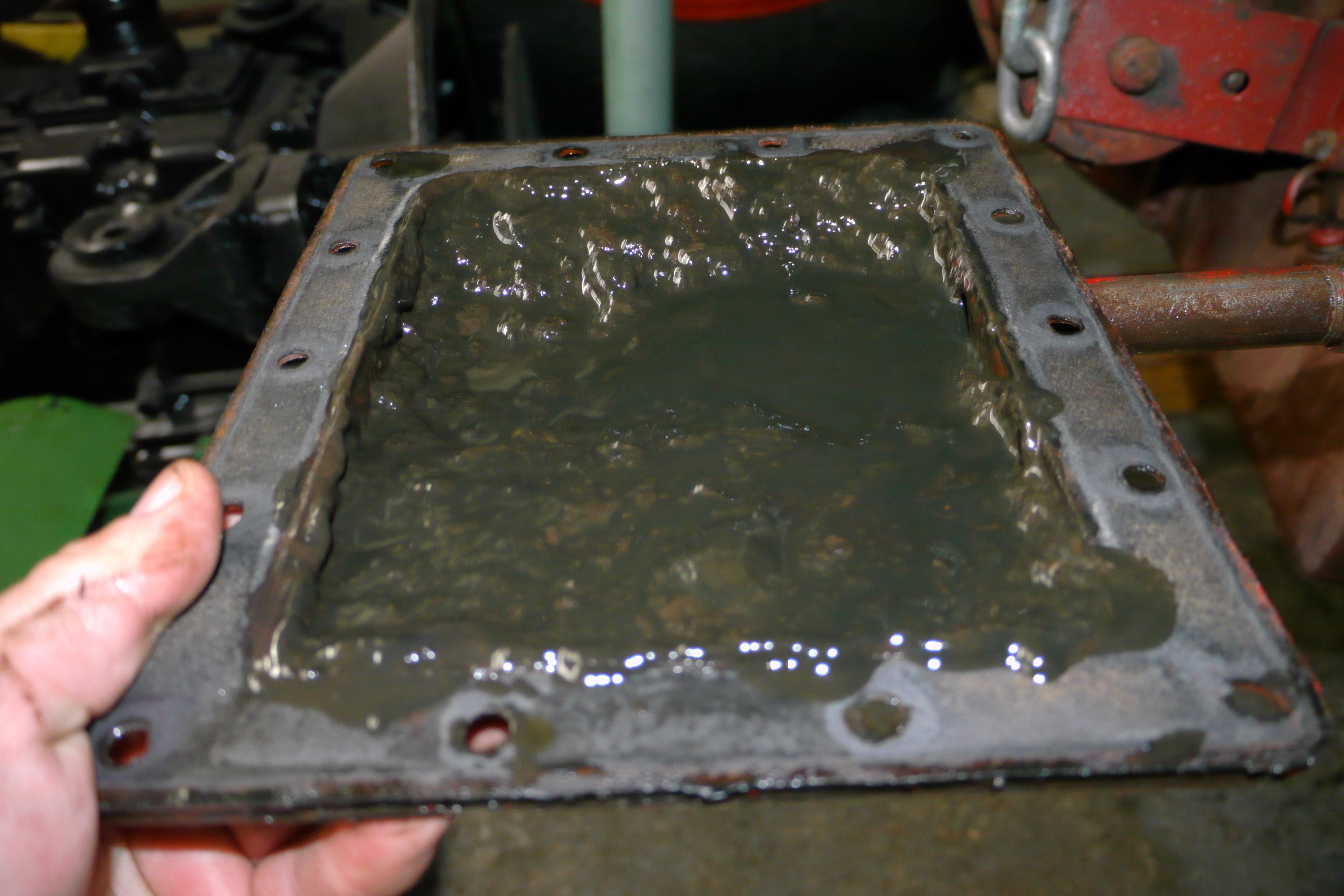
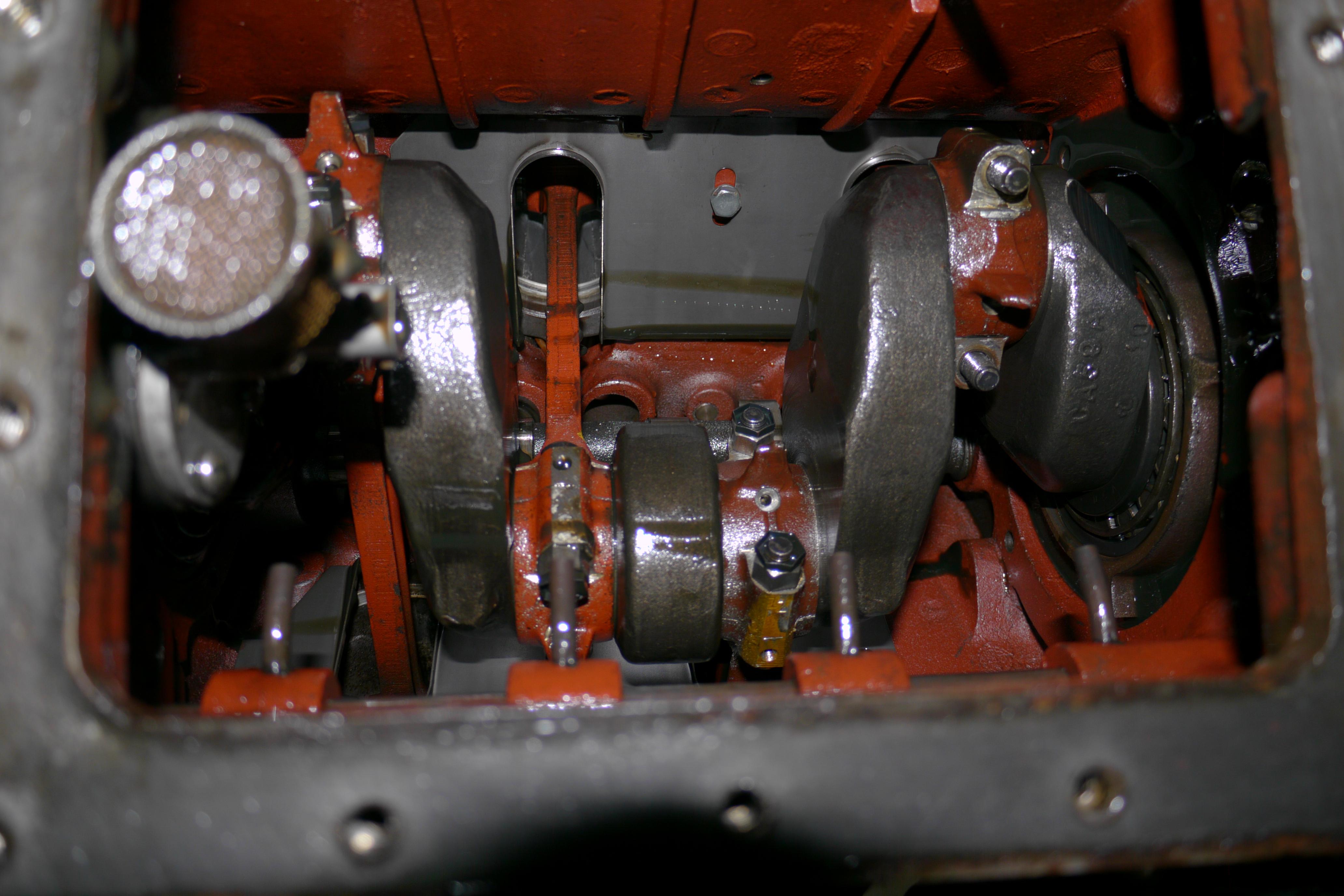
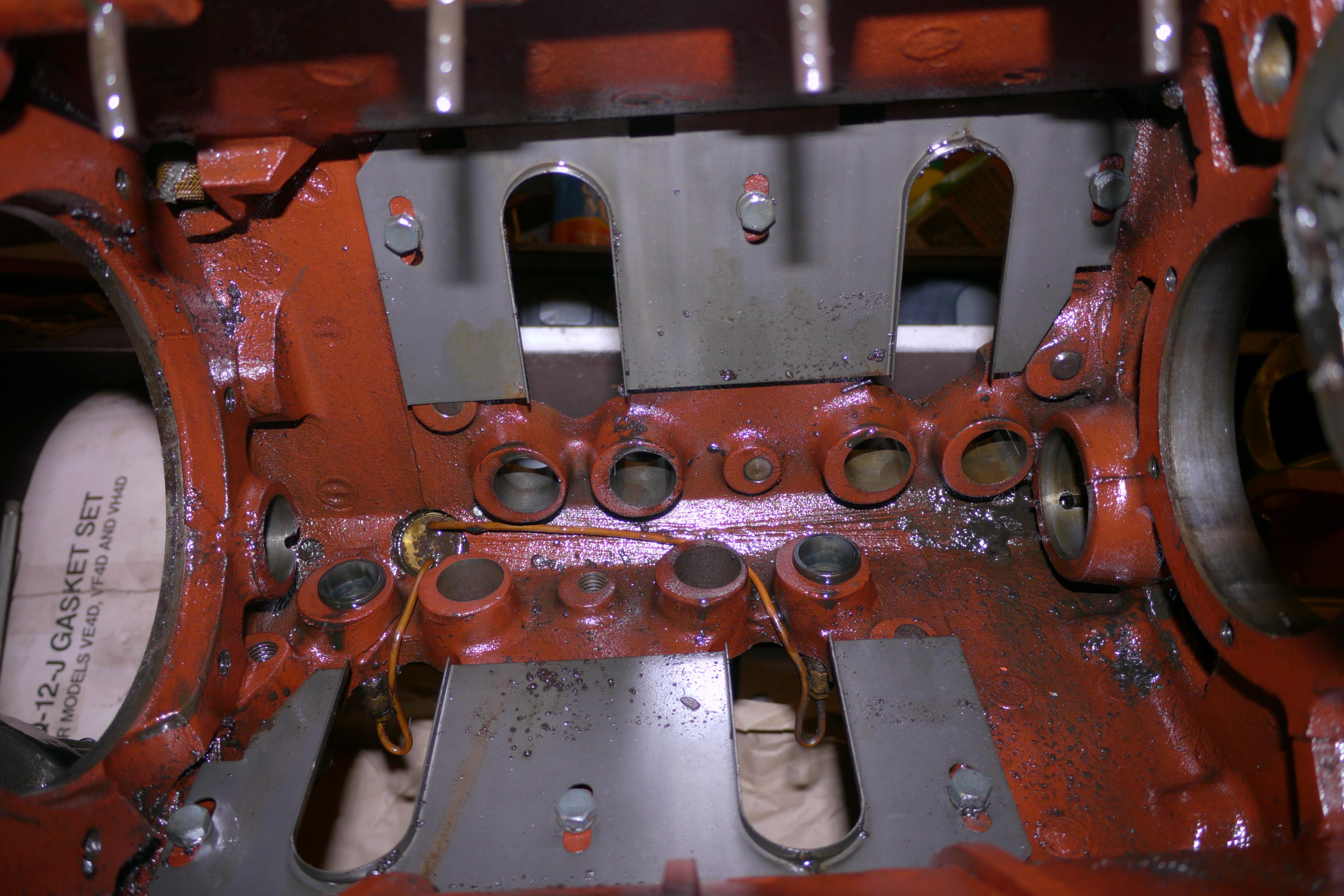
I started off by removing the oil pan and inspecting the underside of the engine. The oil pan on this engine was full of dirty greasy sludge. It was clear that this engine had not run in a very long time. I wiped down the inside of the engine and started checking the big end rod bearings. As you can see in the images below, Wisconsin sealed the inside of their engines with glyptal, a red insulating varnish originally designed to be used on armatures of electric motors. The glyptal varnish actually seals the pores in the rough cast iron block and allows oil to flow faster to the oil pan where it can be sucked up and pushed back through the engine again. It also keeps oil from picking up any left over residual iron grit and debris inherently found in the sponge like cast iron.
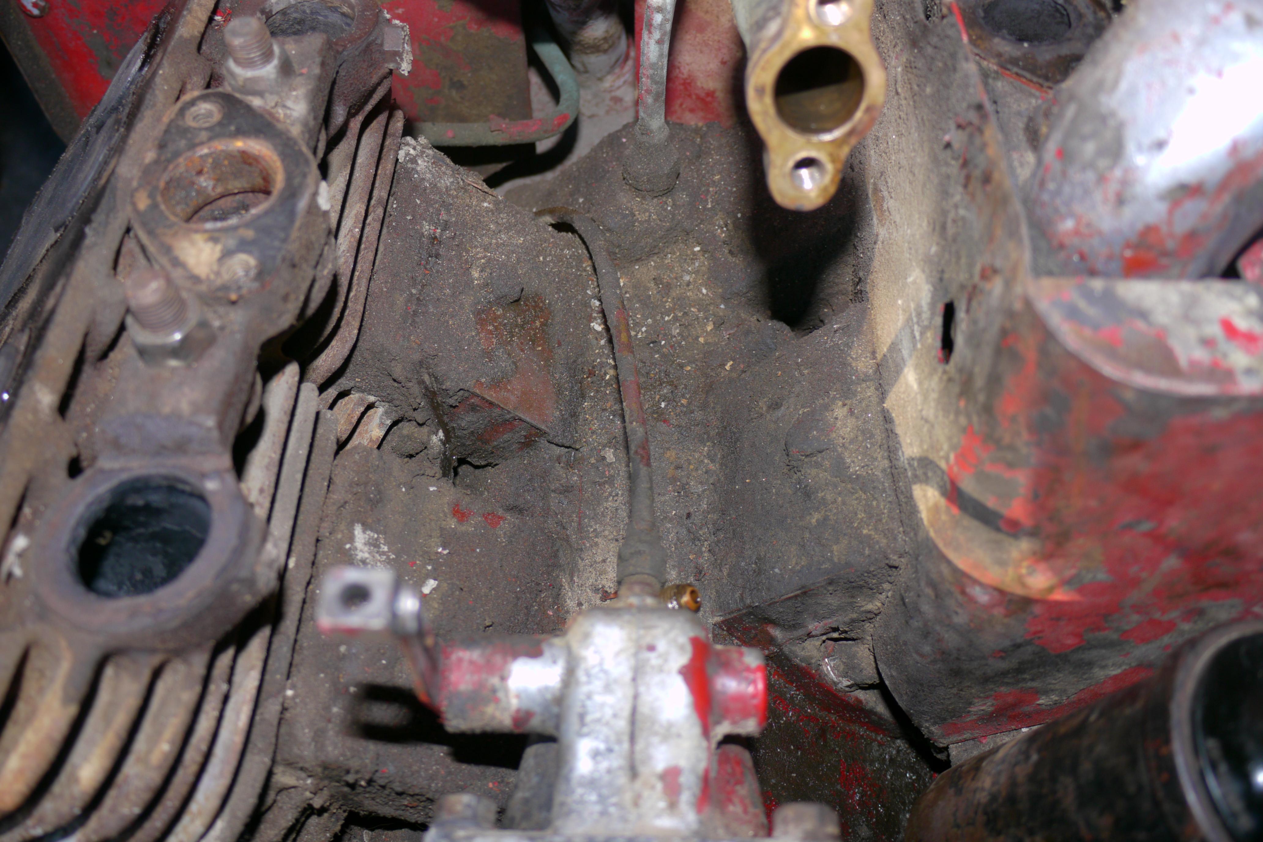
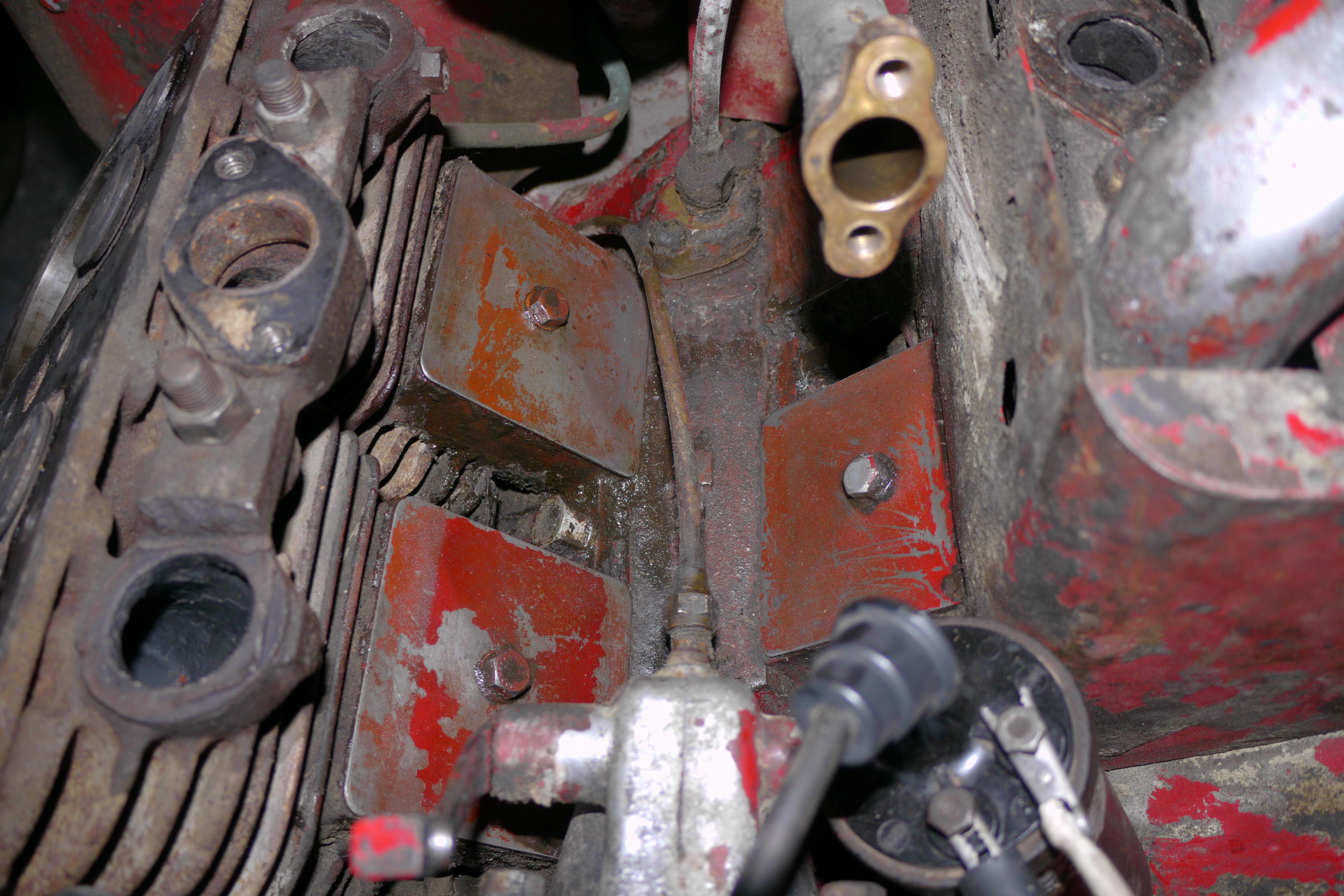
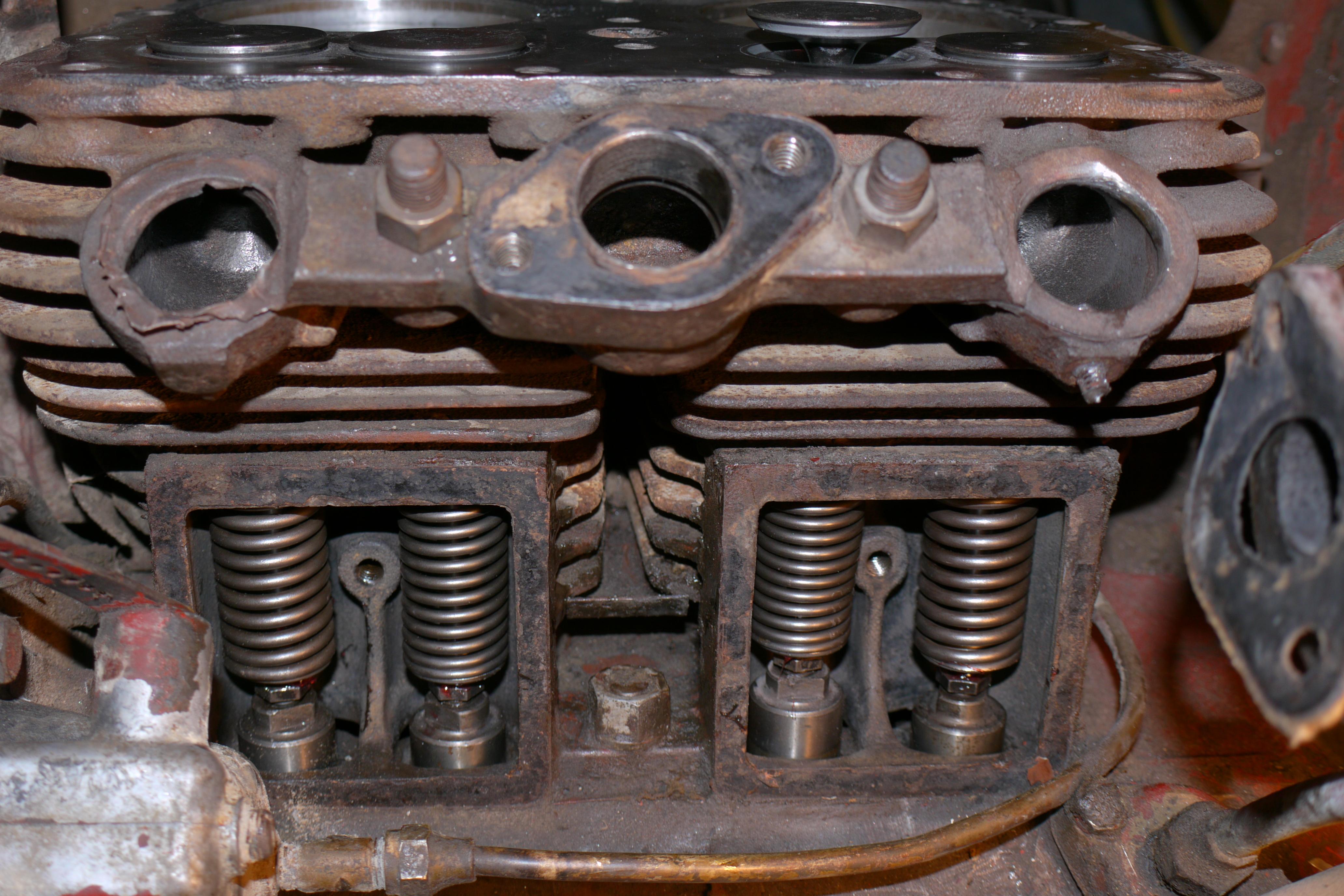
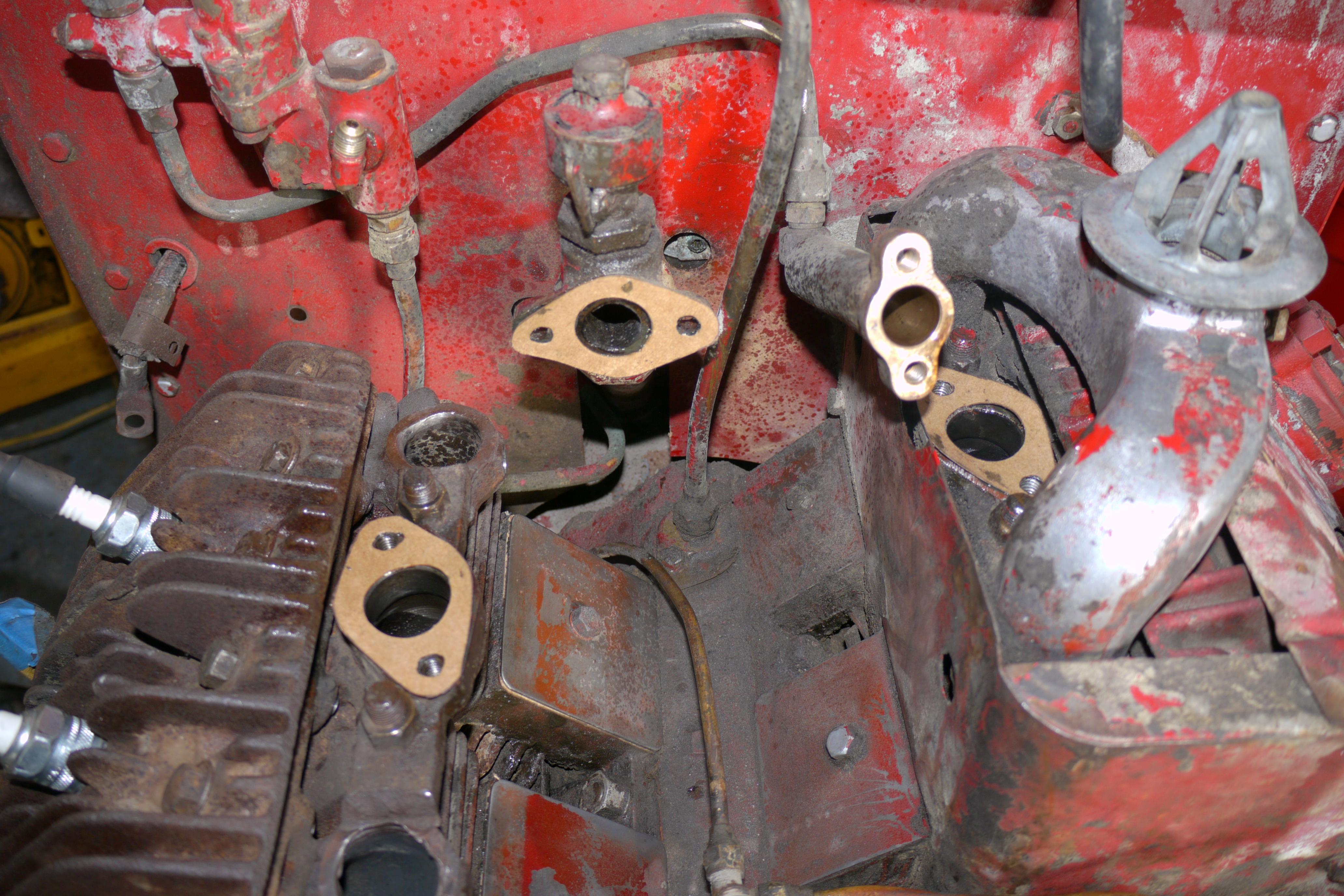
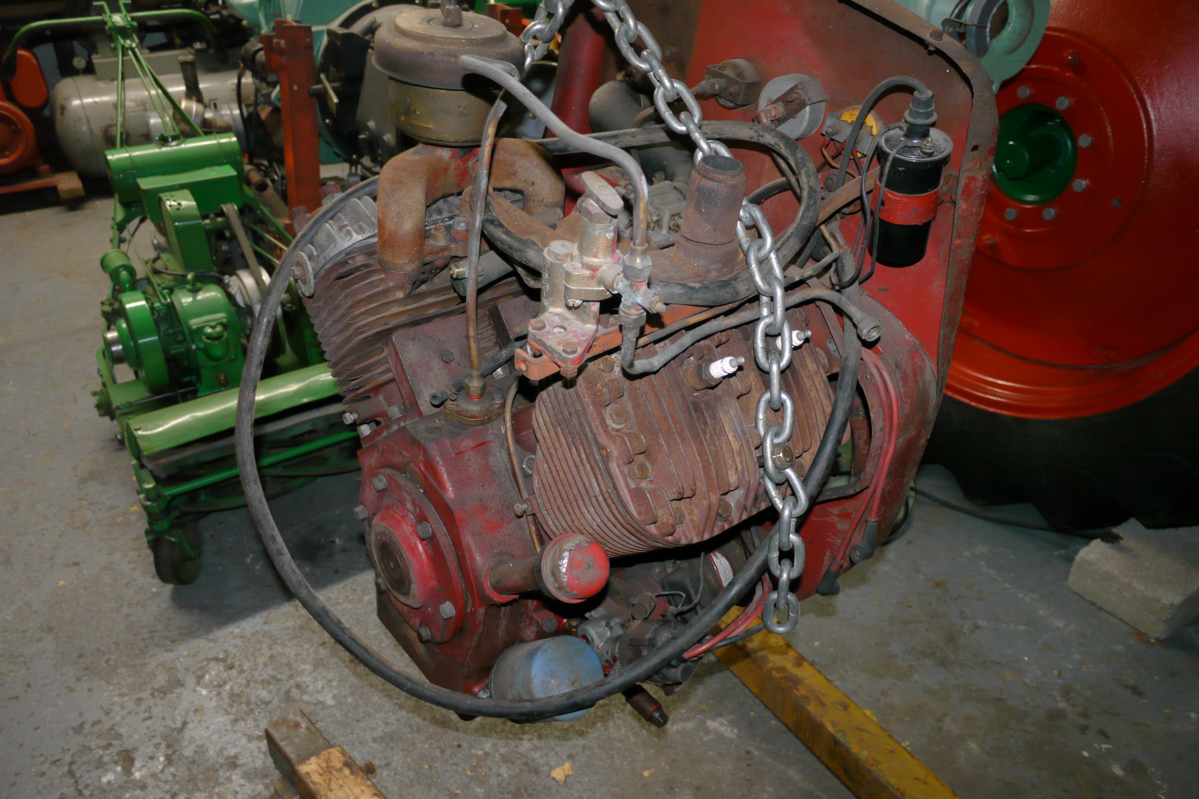
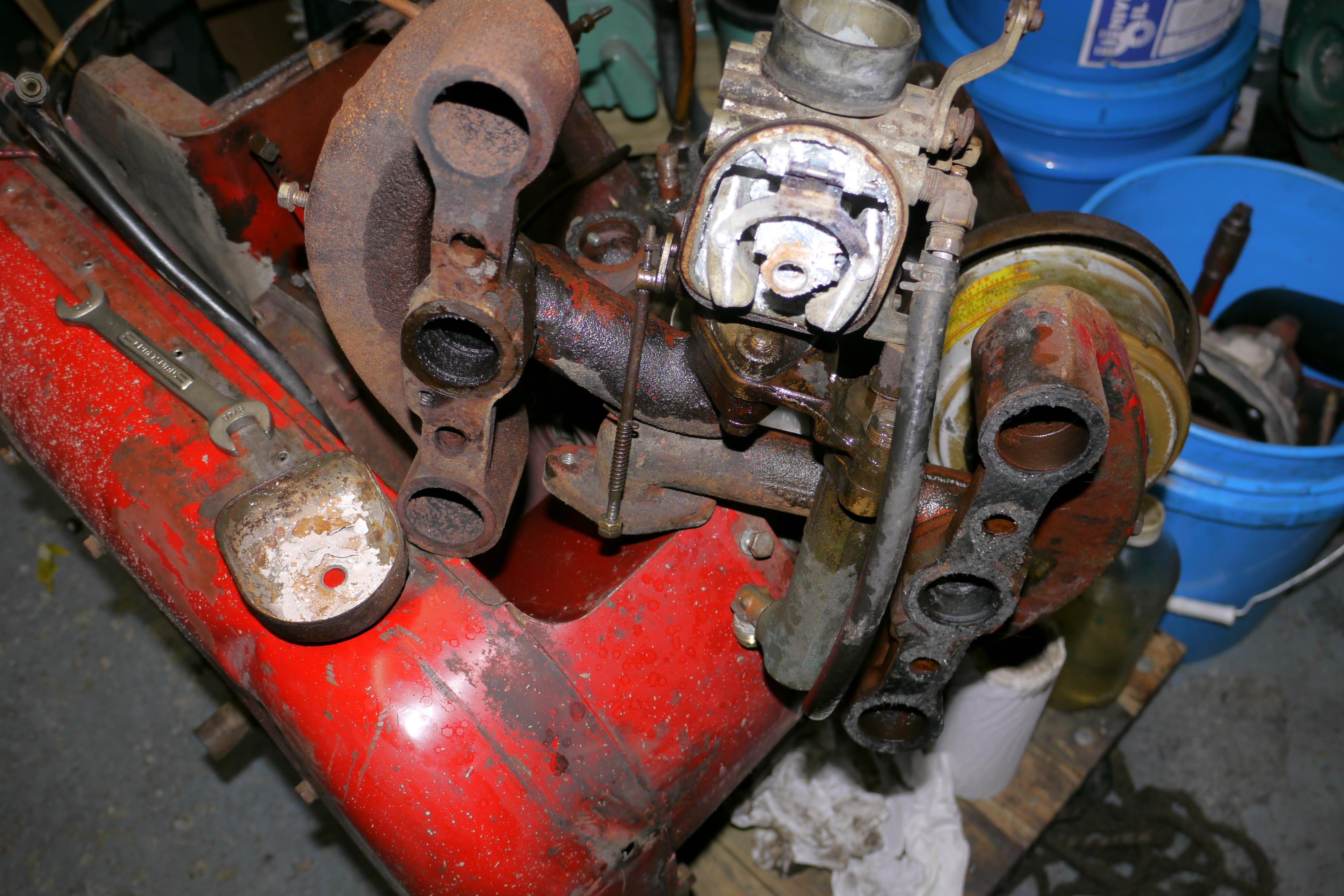
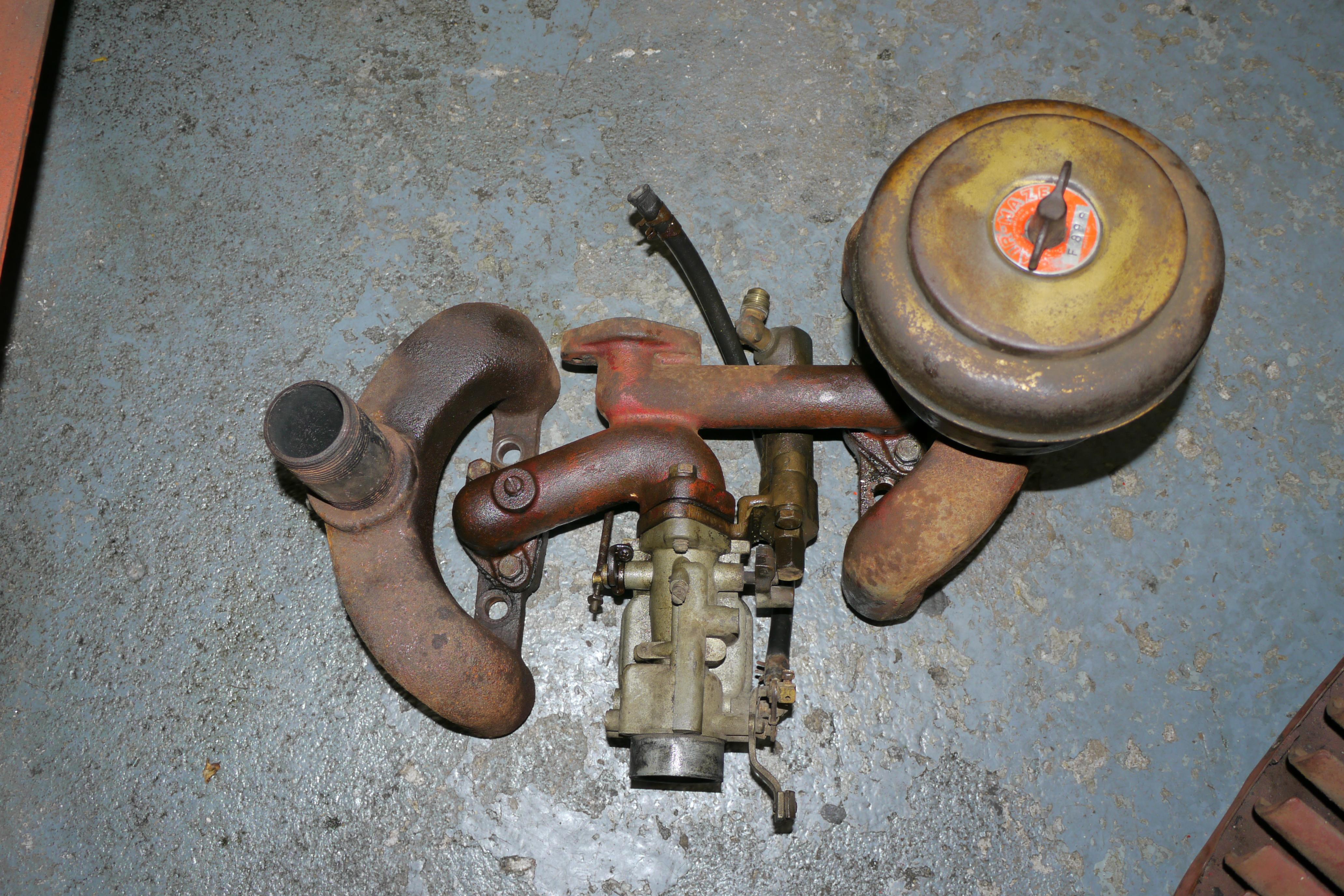
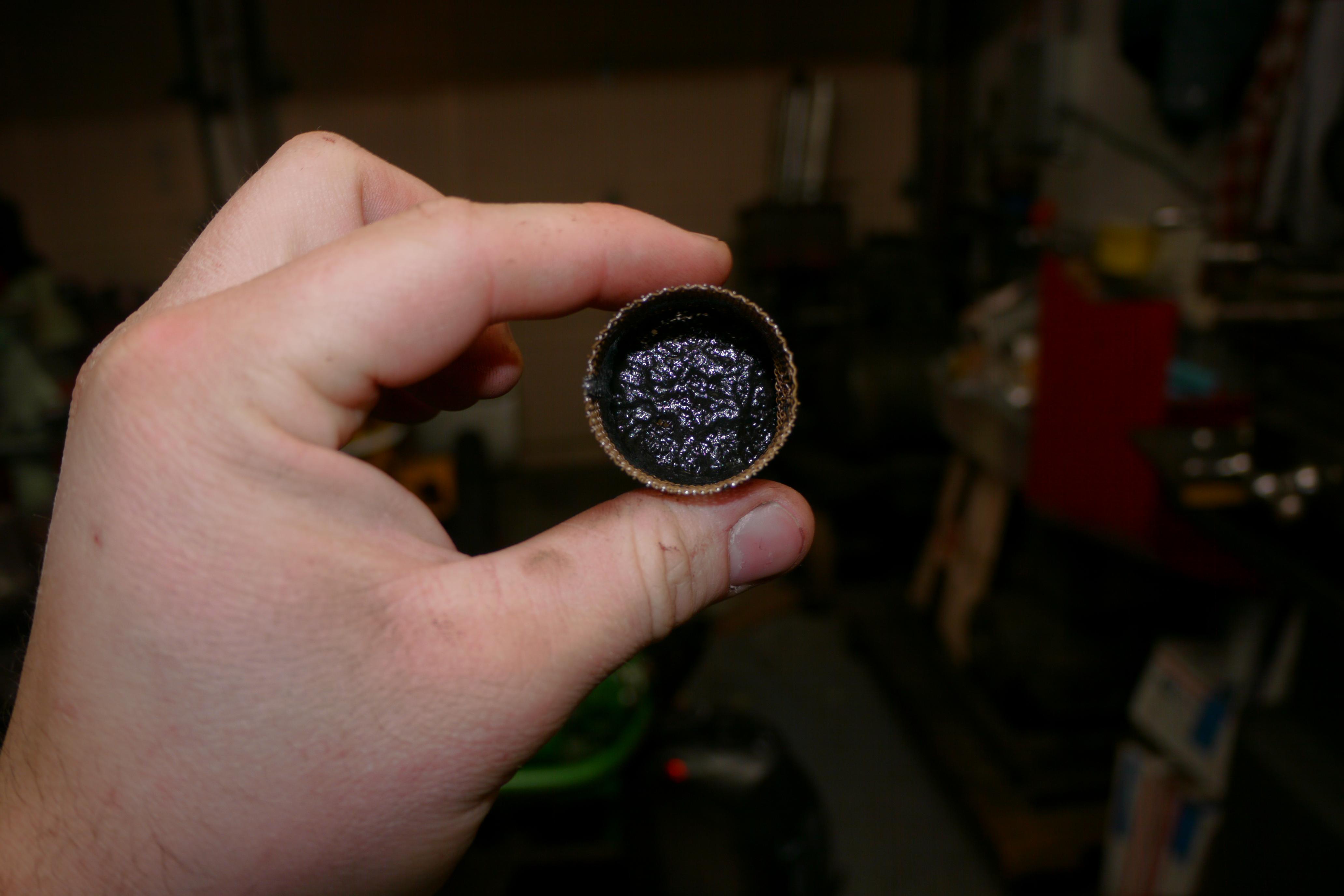
In order to proceed, it is necessary to remove the intake/exhaust manifolds from the top half of the engine. Because this engine is a highly modified VP4, it has Schramm specific intake and exhaust manifolds. On a factory VP4 engine, the exhaust manifold would have wrapped around and collected from all four exhaust ports. You can clearly see that Schramm retained Wisconsin’s method of securing the manifolds to the engine. Before removing this set of manifolds I was under the impression that the exhaust manifold on this engine was in good shape, as the other was completely broken off. Disassembly revealed that this exhaust manifold was cracked in four places and warped very badly. Cast iron is not easy to weld, so its repair will be covered later. Like the other compressor, this one also had a lot of corrosion inside the carburetor. The brass floats and aluminum body were white with corrosion. The carburetor is definitely rebuildable, but it will require a few more parts than usual. The air cleaner for the compressor is really neat, its an oil bath Air-Maze filter. Air-Maze filters are crimped perforated steel filters which screen out large materials. In combination with an oil bath setup, it makes for a very efficient air cleaner.
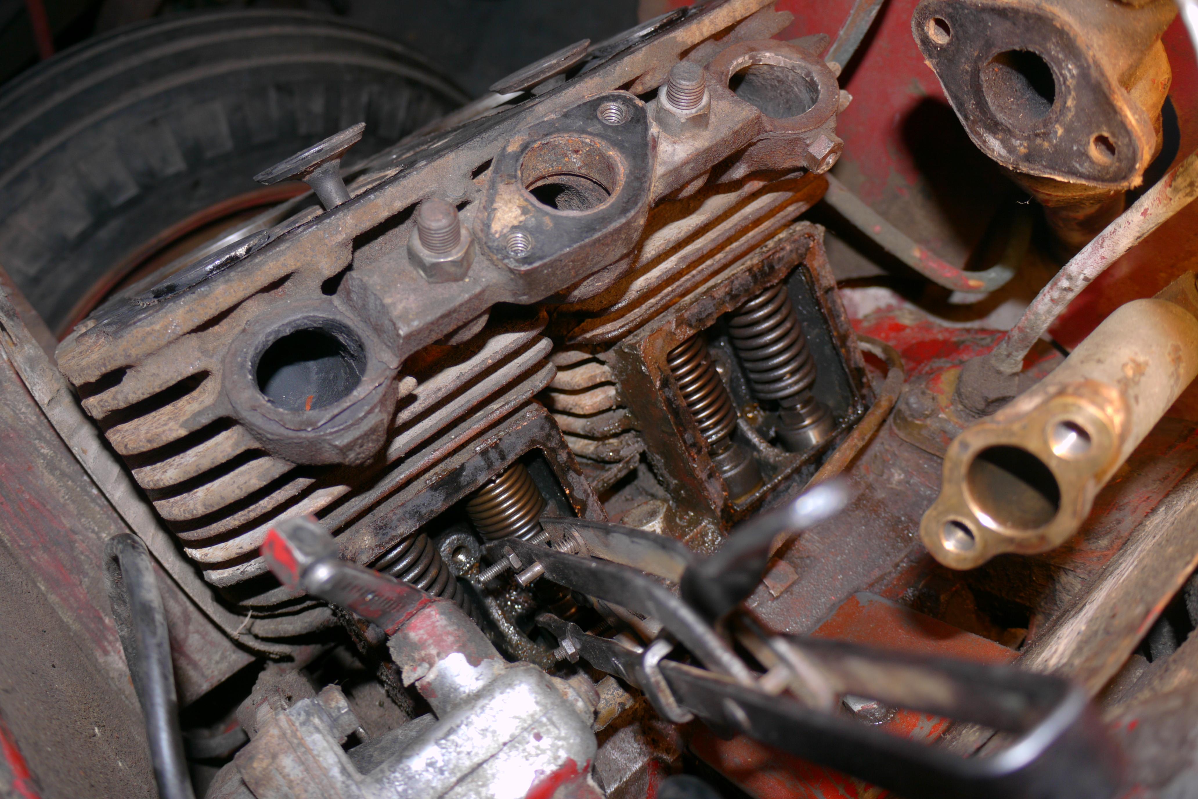
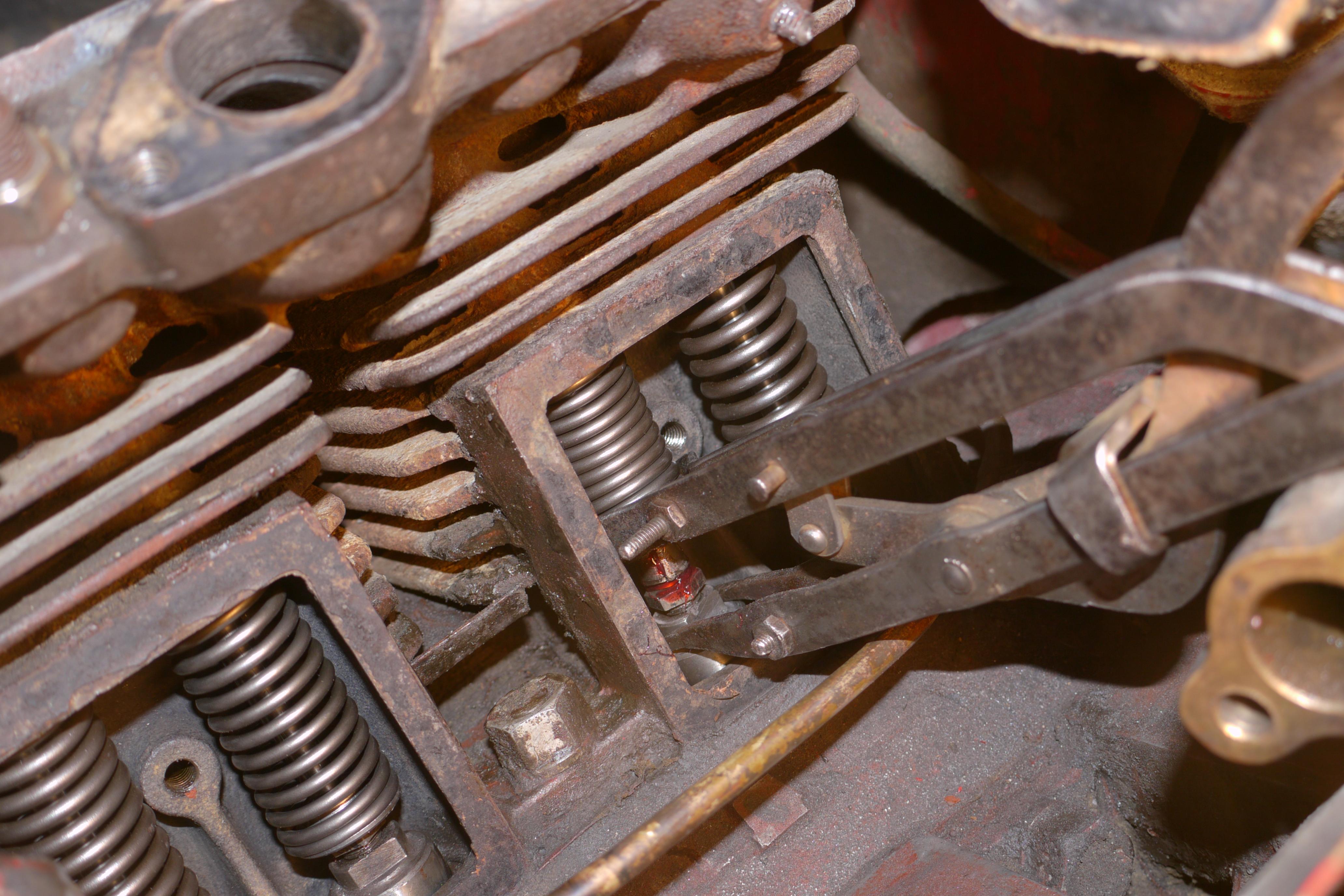
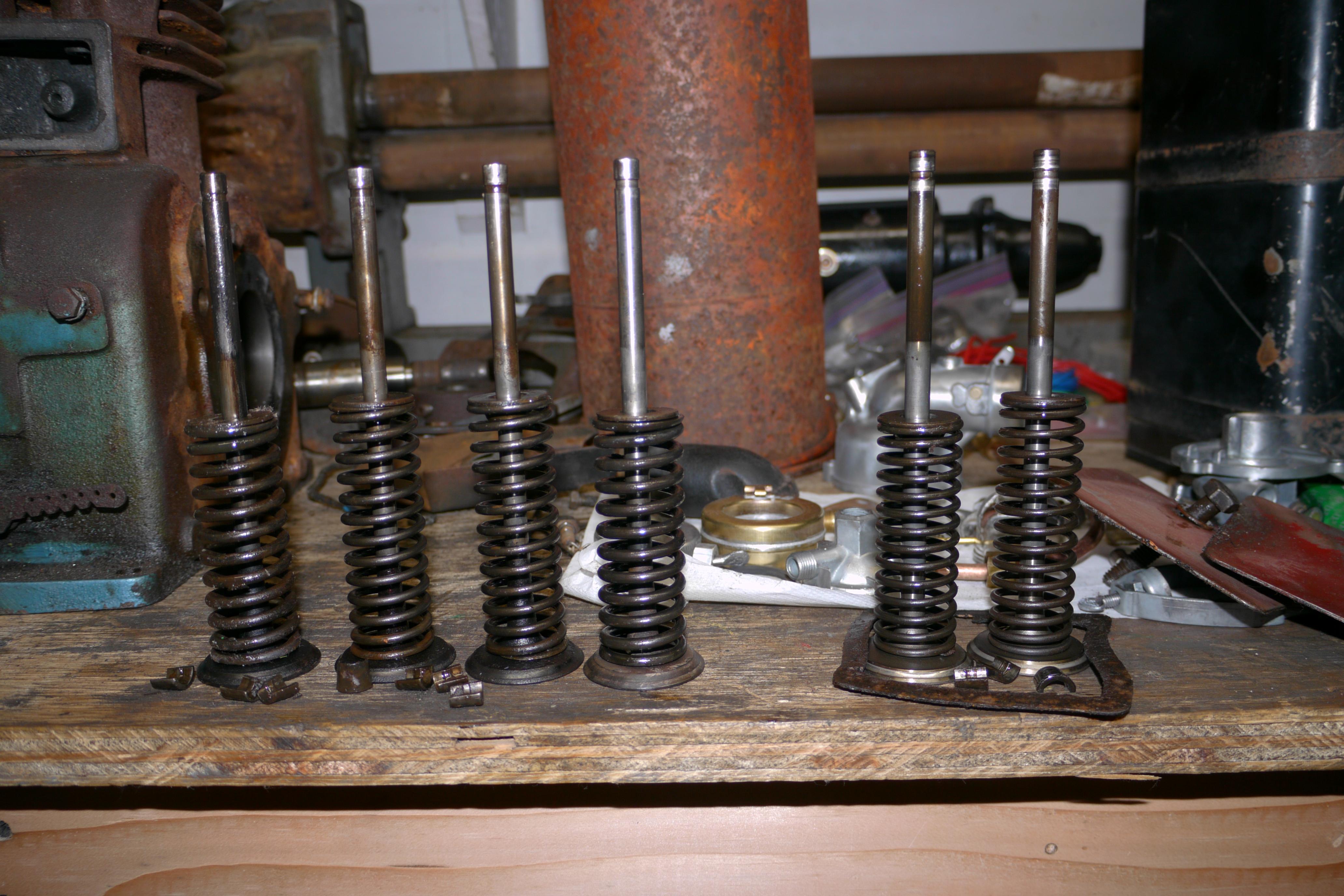
With the intake and exhaust manifolds removed, I opened up the valve covers and removed all six of the engine’s valves. Like the other engine, the valves in this one were sticky. Surprisingly only one of the valves was stuck in the engine. It took quite a while to work the one exhaust valve loose as it was really stuck in the valve guide. I was afraid the valve would pull the guide out of the block! The compressor valves on the other hand were in fine shape, a light lapping is probably all they need.
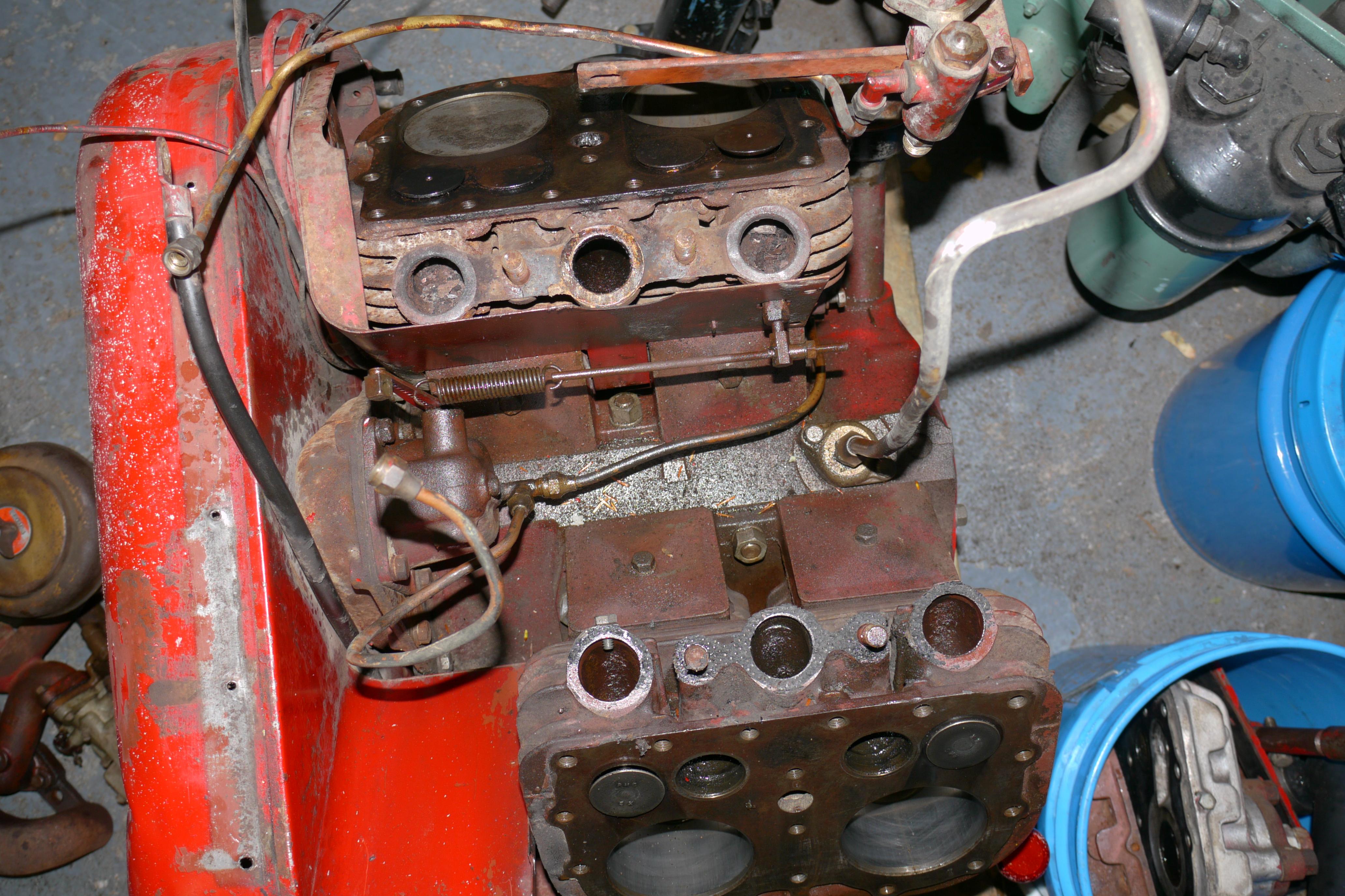
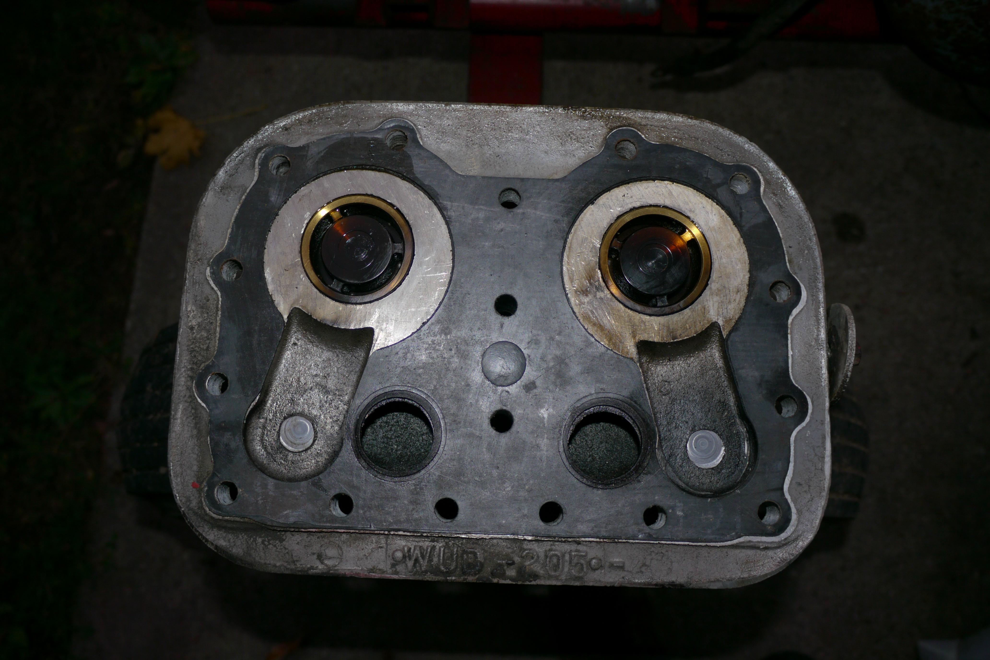
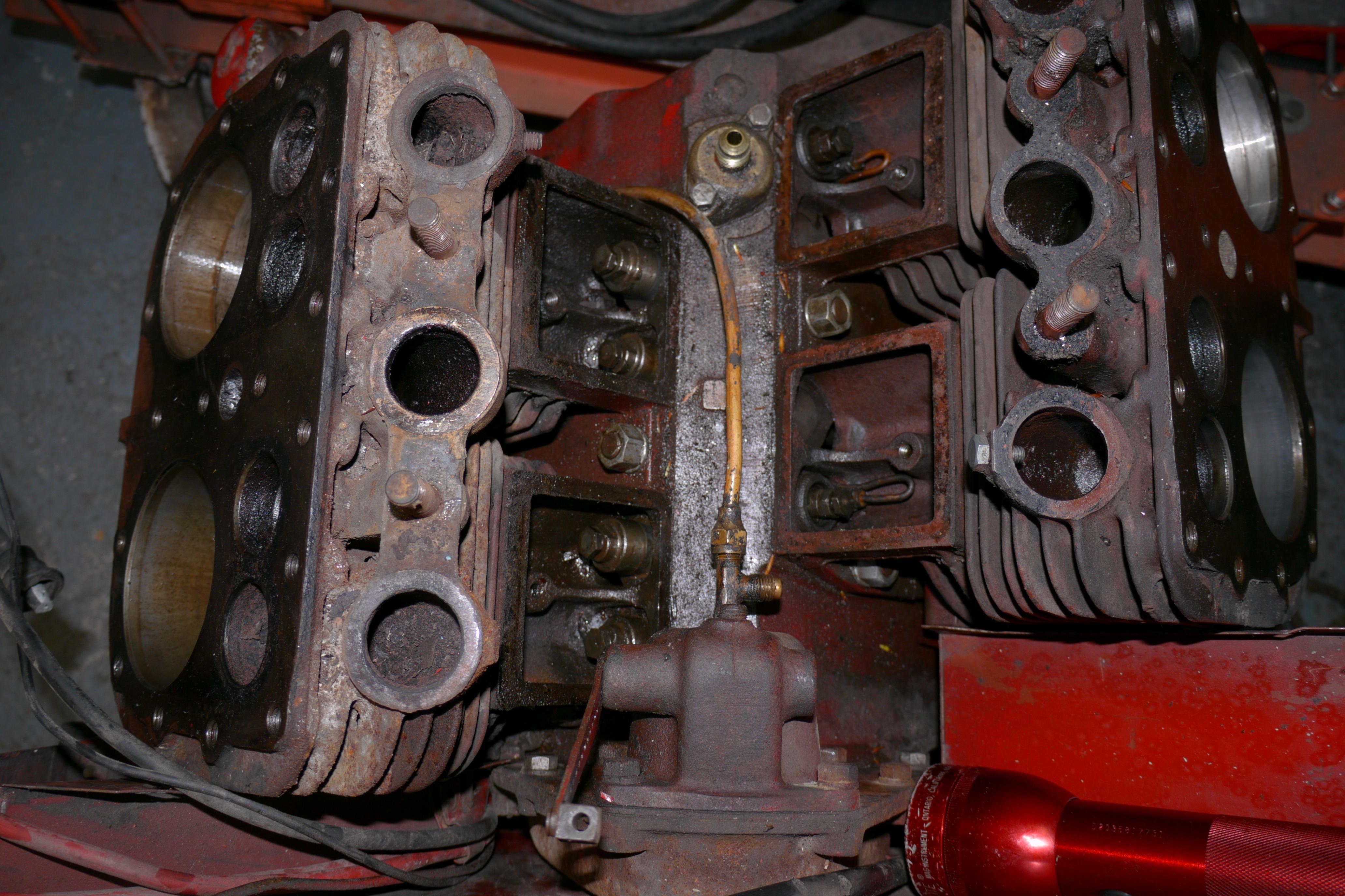
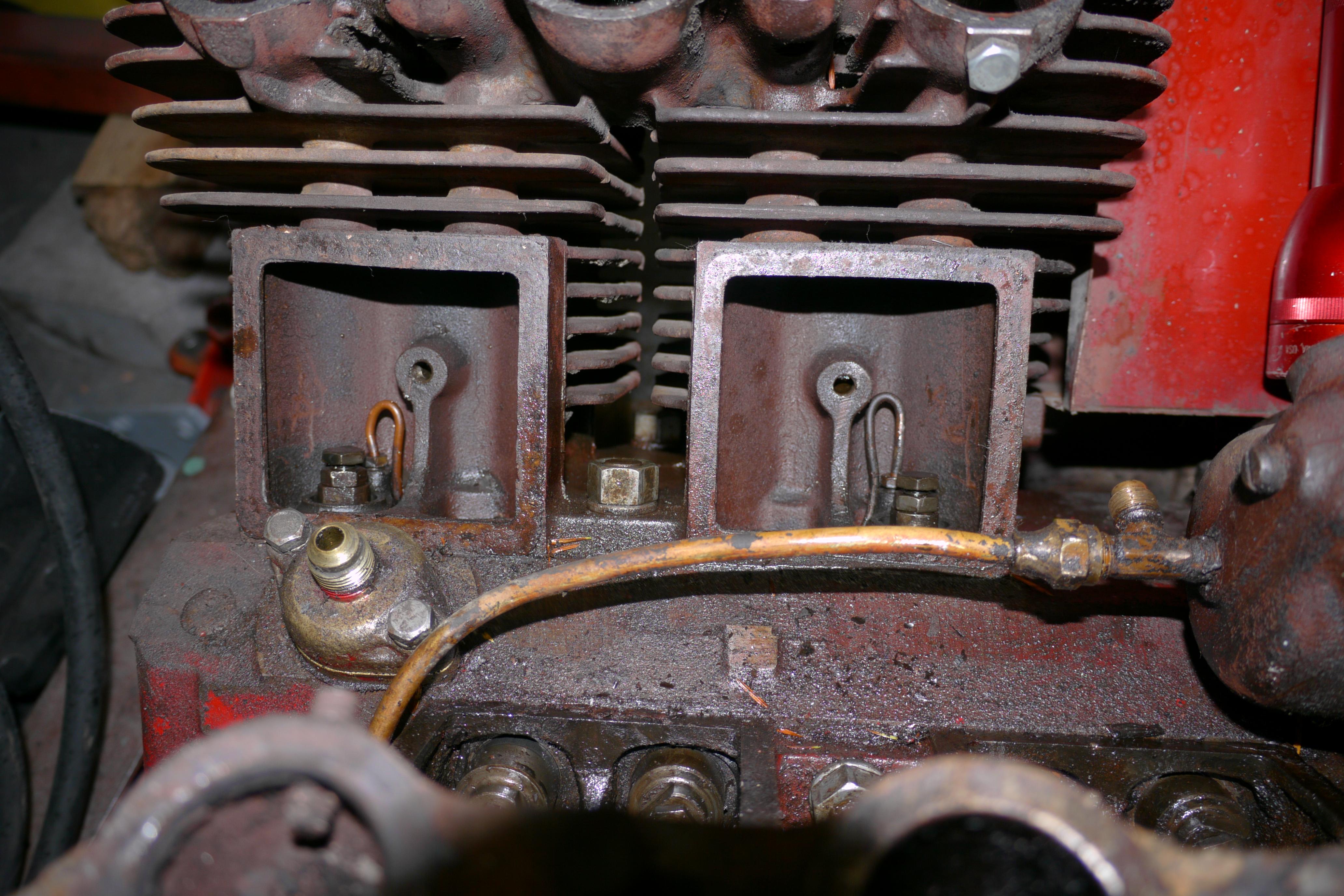
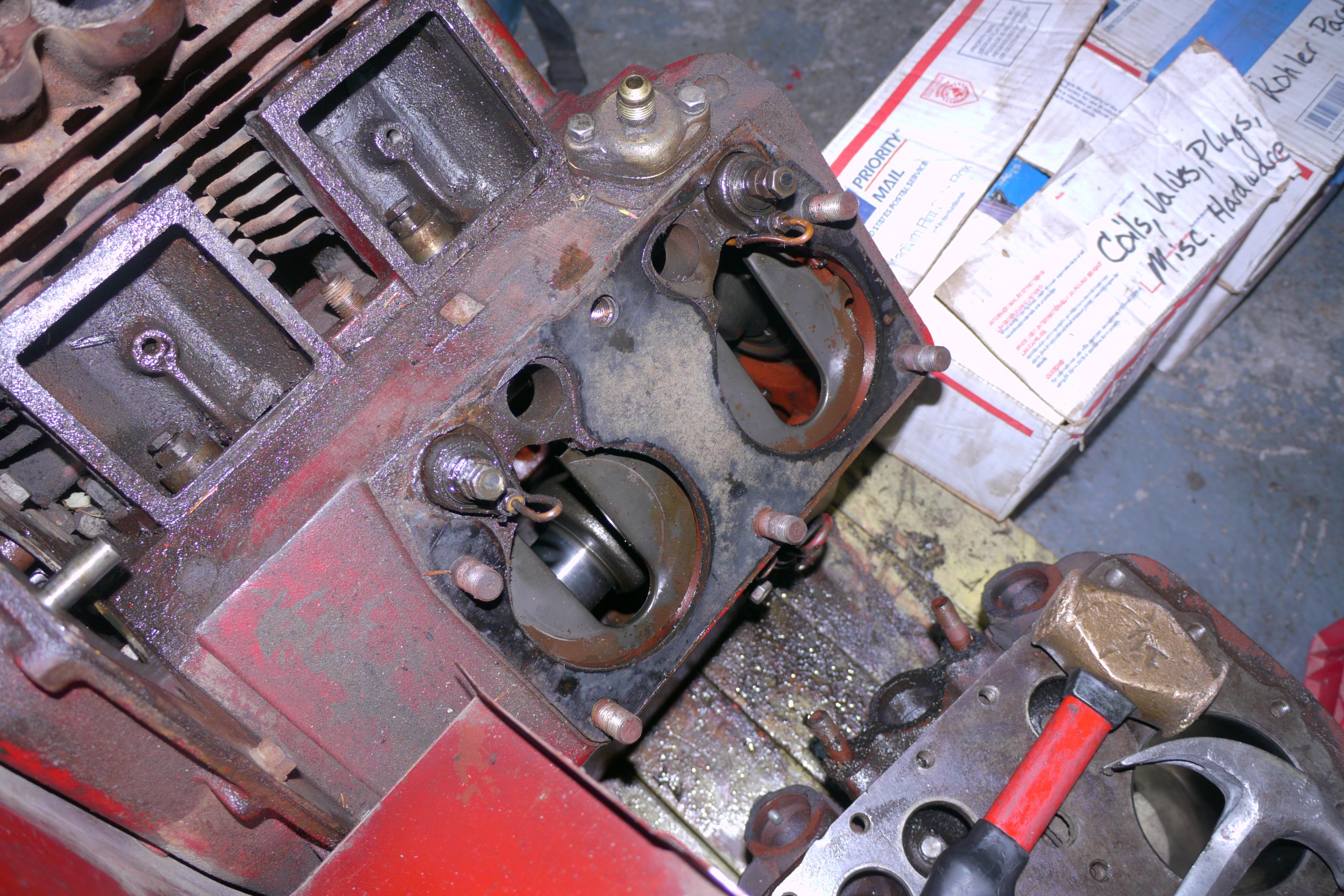
Removing the valve covers unveiled the secret behind Schramm’s internal unloaders. On the top of the block on the PTO side there is usually an elbow adapter for a fuel pump, however this engine has a bronze adapter in its place! This adapter allows a high pressure air line to run from the horizontal receiver (air tank) into the crankcase. This adapter converts a 1/4″ npt pipe fitting into two 1/16″ air lines. These air lines run along the top of the crankcase and up into the valve spring pockets. They run right into a pair of brass valve guides! Schramm designed and manufactured a two piece lifter for this engine, hollow in design with scraper rings and sealing o-rings. When 125psi of pressure in the tank is made, high pressure air runs through the pilot valve and into the adapter on the top of the crankcase. High pressure air is forced between the upper and lower lifters floating the valves for the compressor.
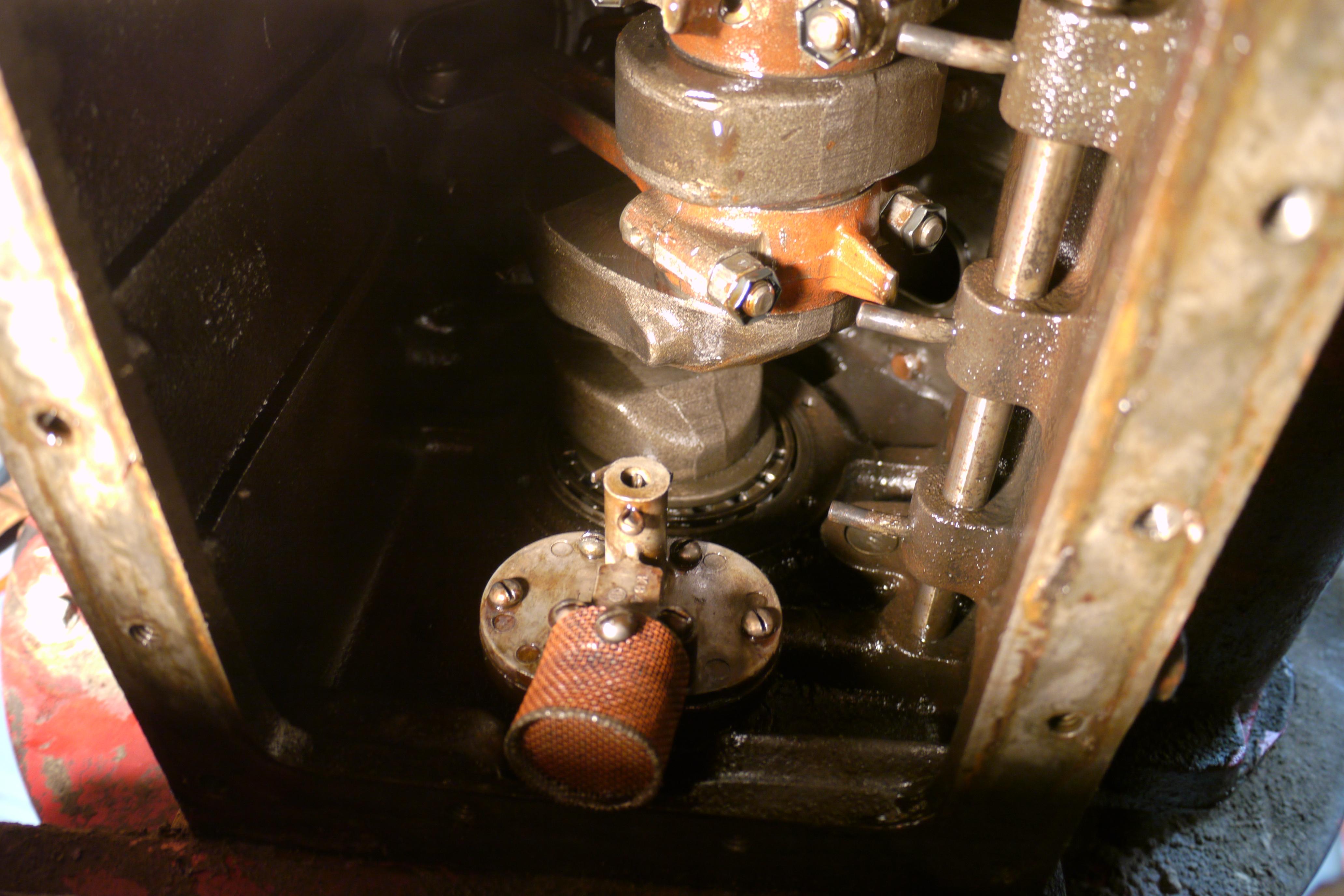
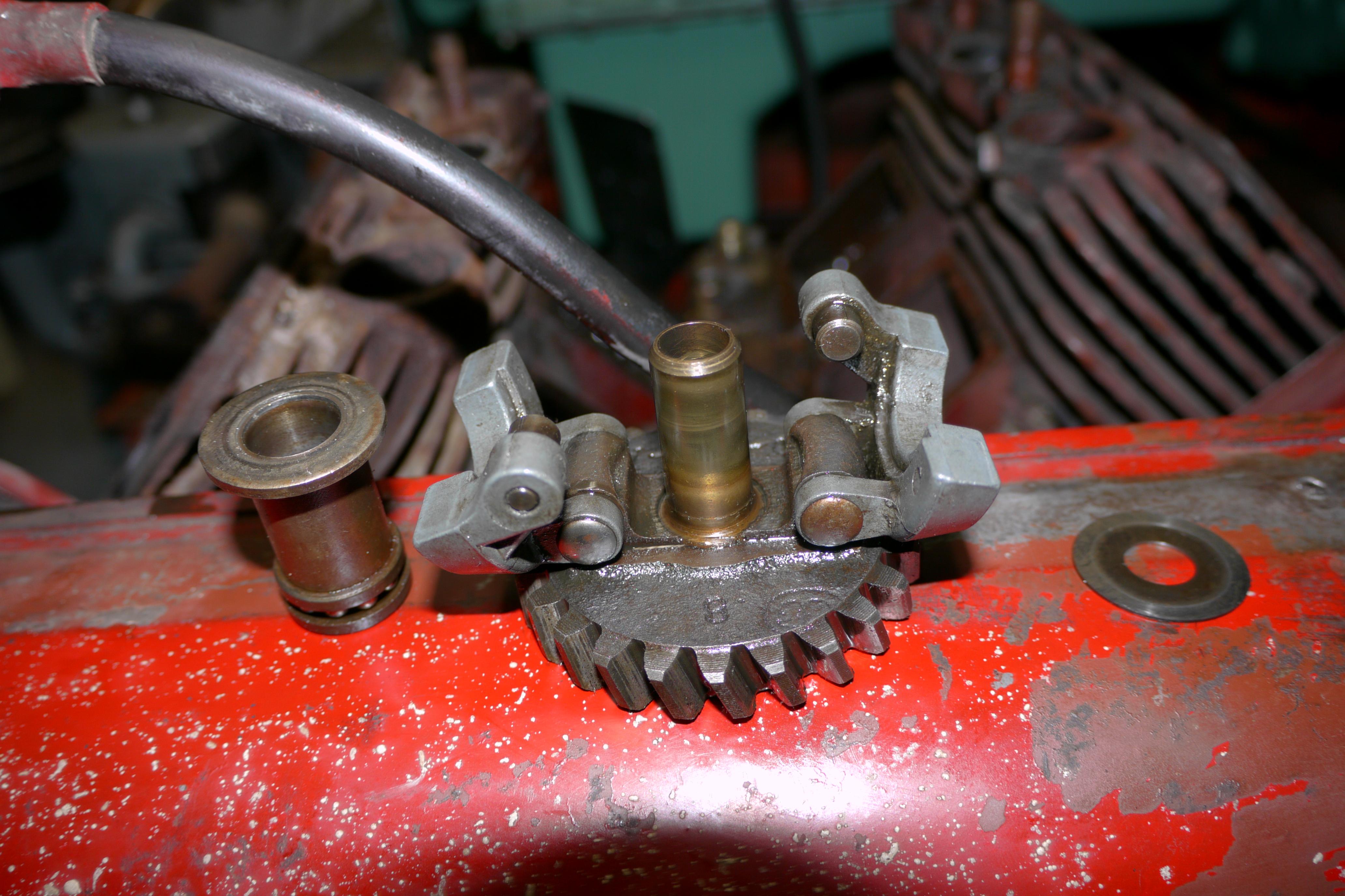
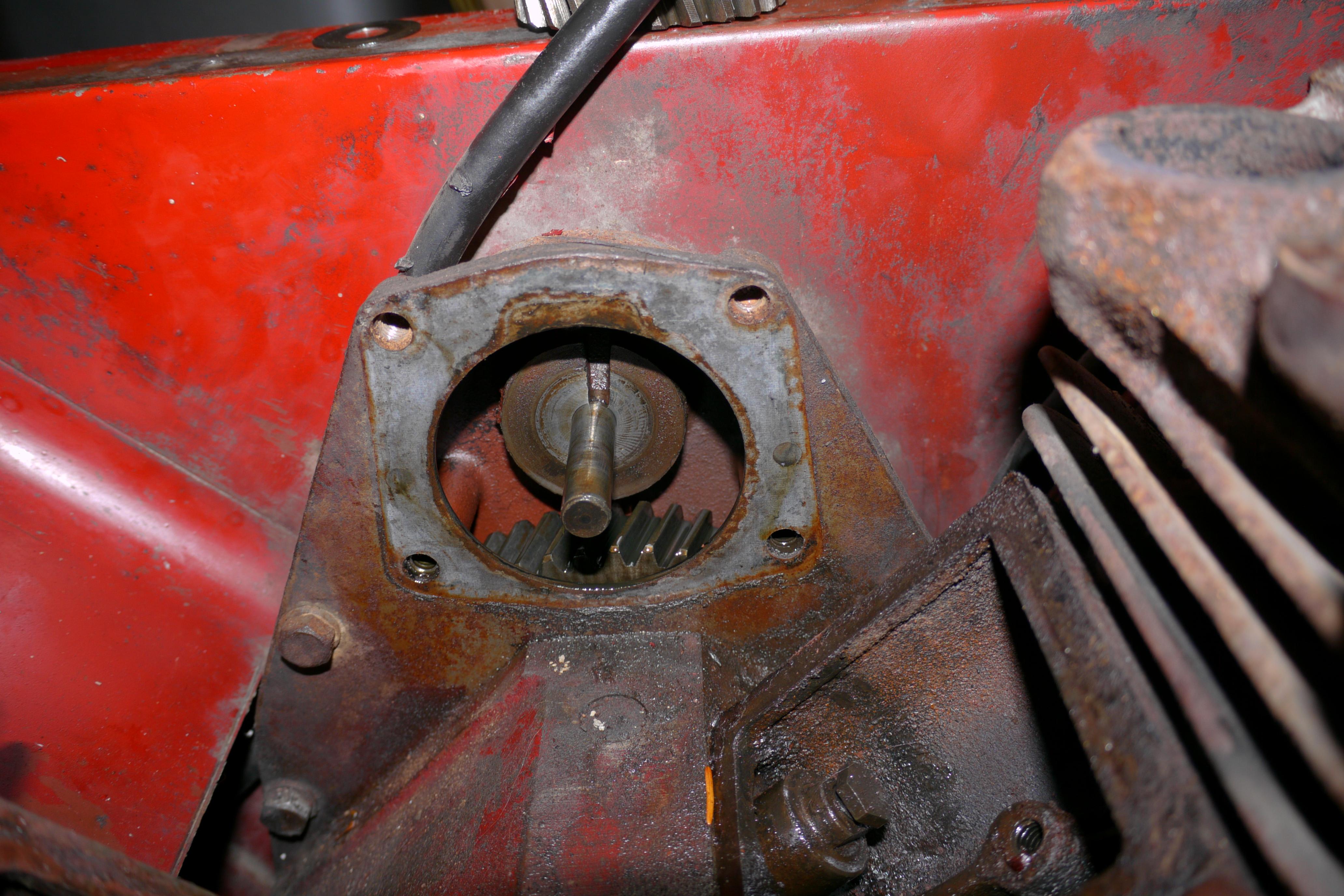
In order to continue disassembling the engine, I had to remove the governor assembly from the engine. The governor is conveniently located in the top/front-center of the engine and is lubricated by a low pressure oil line from the pressurized oil gallery on the side of the block. Pulling the governor housing revealed that the governor bushing was well worn from the flyweights moving in and out over the years of its use. The bushing will have to be replaced before the engine is put back together. It is pretty normal for the governor bushing to be worn out because it is located at the top of the engine where oil pressure is minimal. Although there is a pressurized supply line of lubricating oil which feeds the governor, a worn oil pump can cause premature wear since the engine only operates with about 5-7 psi of oil pressure. If we flip the engine over you will see what I am talking about. The oil pump in this engine is a gear driven pump with a completely clogged intake screen.
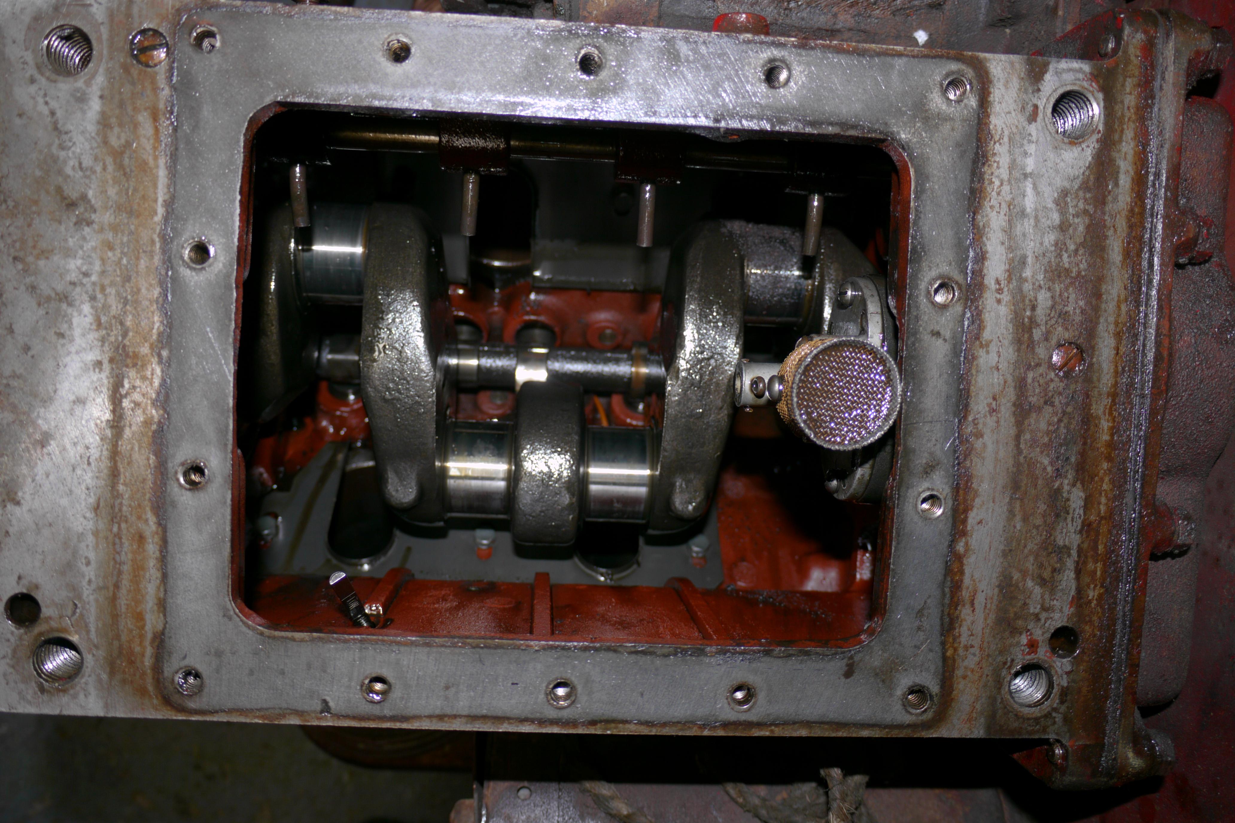
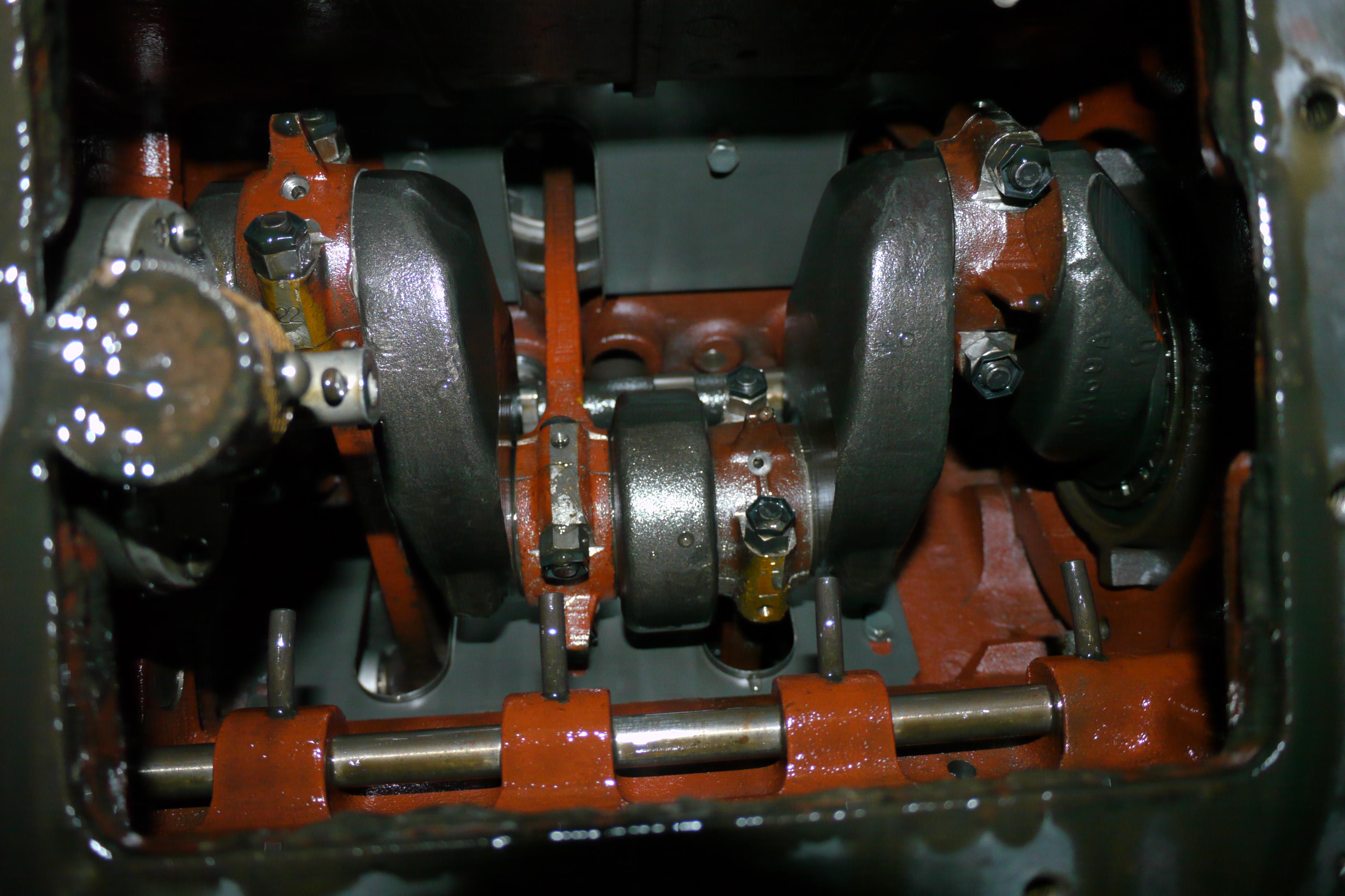
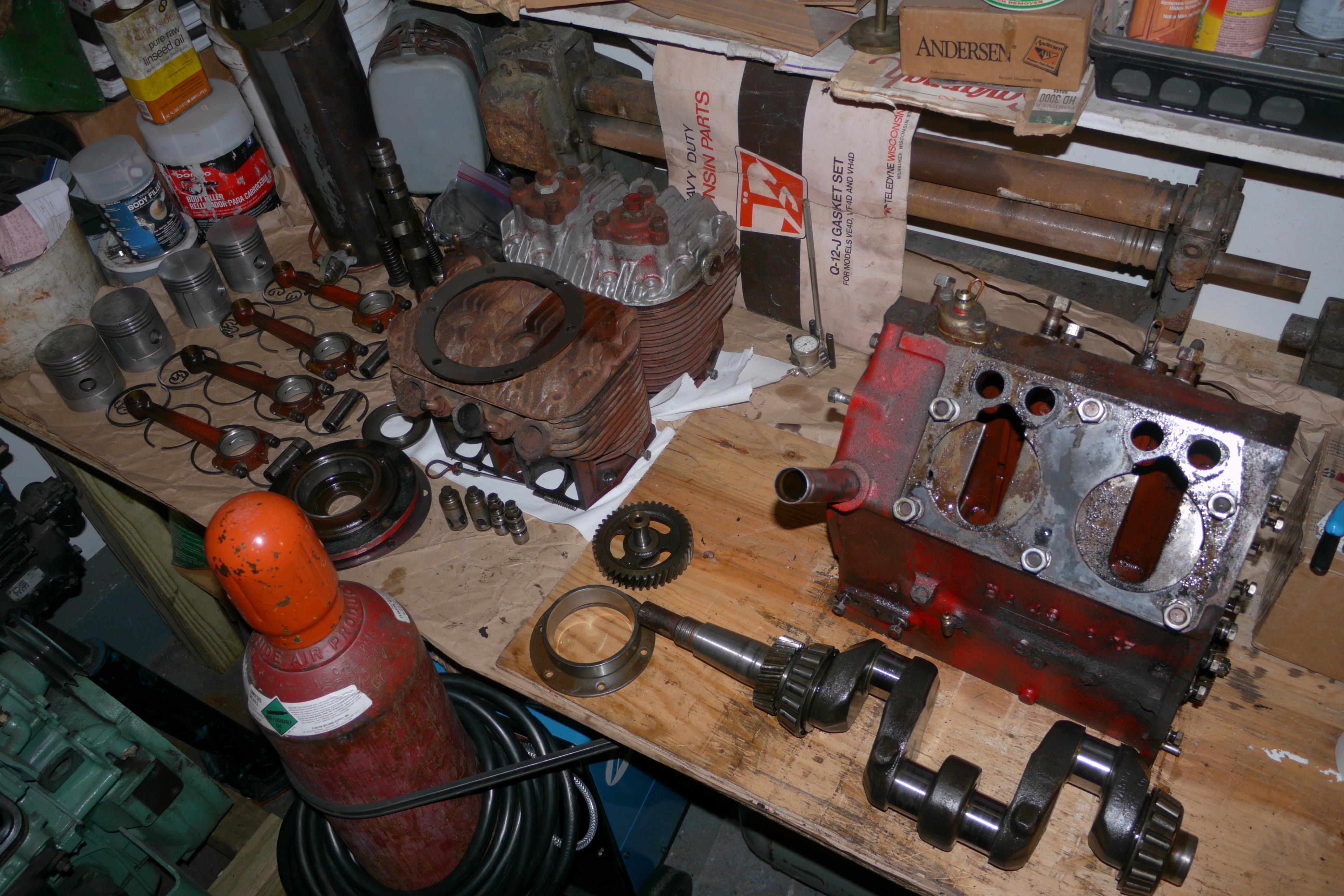
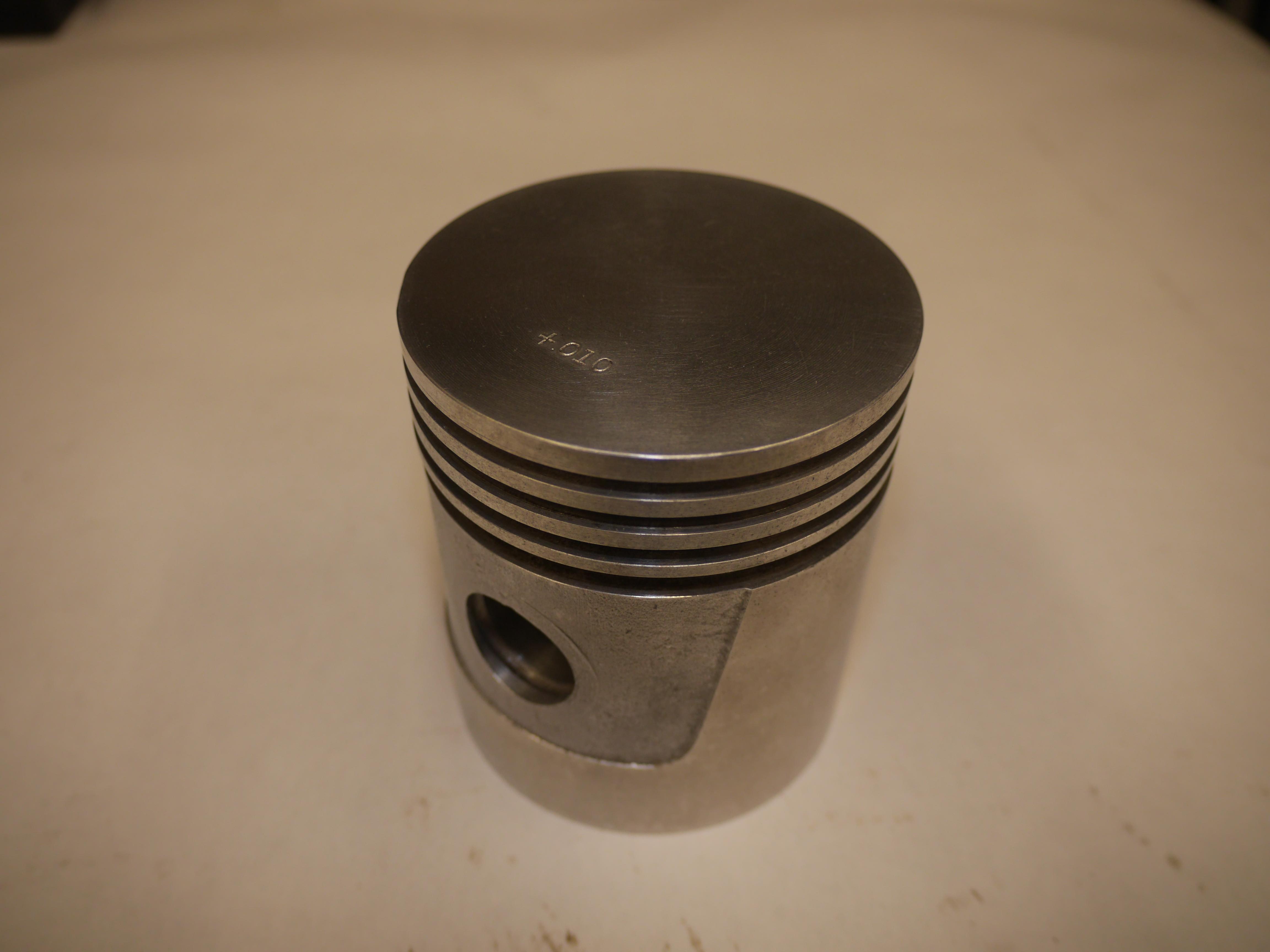
In my opinion Wisconsin built the finest small engines, they are incredibly tough, overbuilt and designed to run for a very long period of time. Some of the Wisconsin engines in my collection have well over 10,000 hours of run time on them. Their incredible life is mainly due to their use of the finest materials. Every Wisconsin heavy duty air cooled engine has Timken tapered roller bearing mains, babbitt or copper jacketed rod bearings, pressure lubrication, forged steel connecting rods, Alcoa aluminum/lynite pistons and stellite hardened valves. This engine is no exception and has all of the heavy duty features a Wisconsin engine was known to have. You can see how overbuilt these engines are just by looking at the rotating assembly. The pistons, connecting rod and main bearings are far larger than what might be found in competitors engines. Large bearing surfaces allow for better heat transfer, a larger film of oil for the rod to run on, and a better transfer of power. The long connecting rods are just an example of how their engines were designed for low rpm high torque applications. Although babbitt bearing designs have gone to the wayside, there is certainly nothing wrong with them. As long as the lubrication oil supply is maintained and clean, and the oil pump is working like it should, babbitt bearings will share the same life as a copper jacketed replaceable bearing. The only major difference is the need to shim the connecting rod caps correctly in a babbitt bearing application. Babbitt bearings are poured lead bearings which are line bored to the size of the rod journal. From the factory there are usually a few thin brass shims between the connecting rod and cap for future adjustment as the bearing wears. To my surprise the babbitt bearings on all of the connecting rods were in good shape. Usually they are chewed up from contaminated oil, or from over torquing of the connecting rod cap nuts. All four of the connecting rods would be perfect for re-use if I did not already have four brand new connecting rods on the shelf. I will be using those, since one of the original connecting rods had a dented web, which could potentially weaken the rod. The pistons at first look unusual, however they are period correct split-skirt pistons.
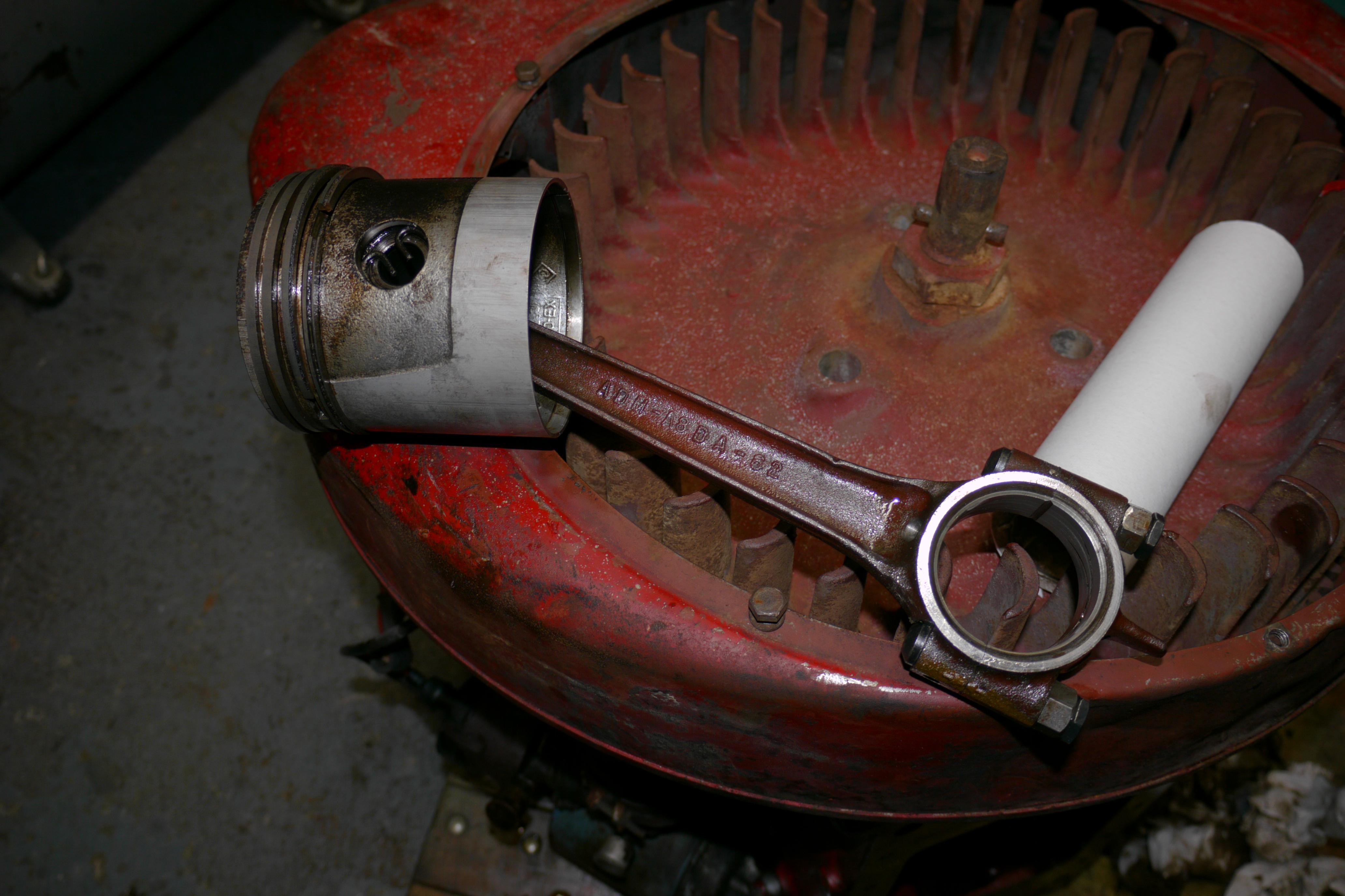
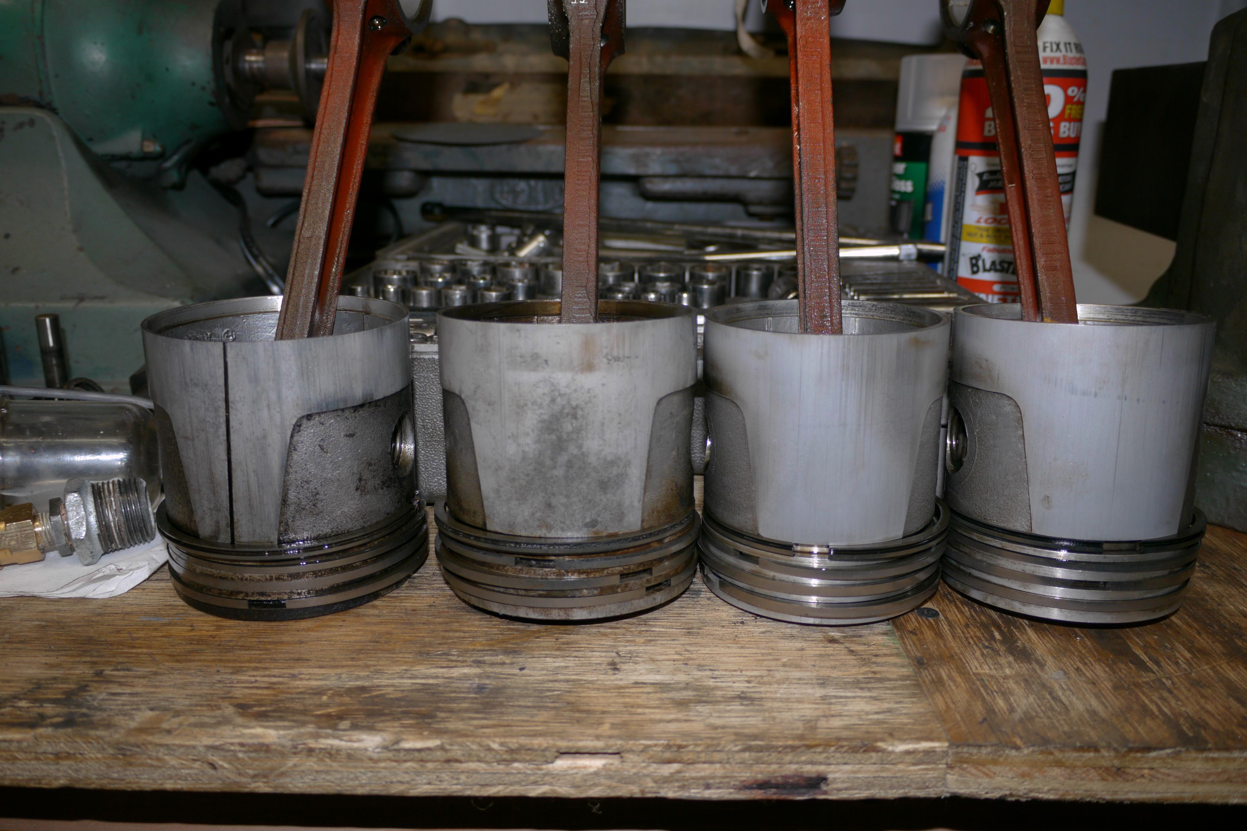
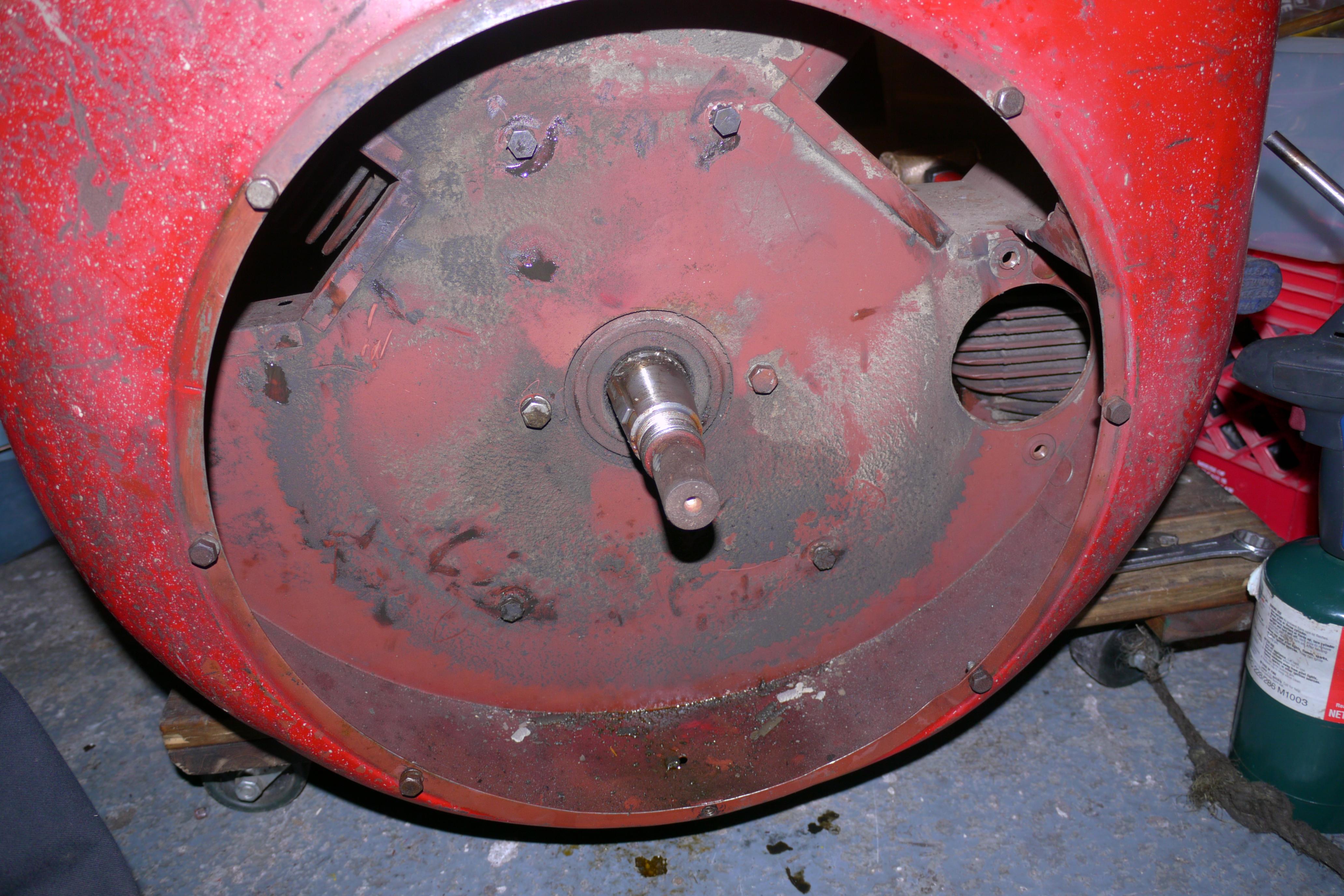
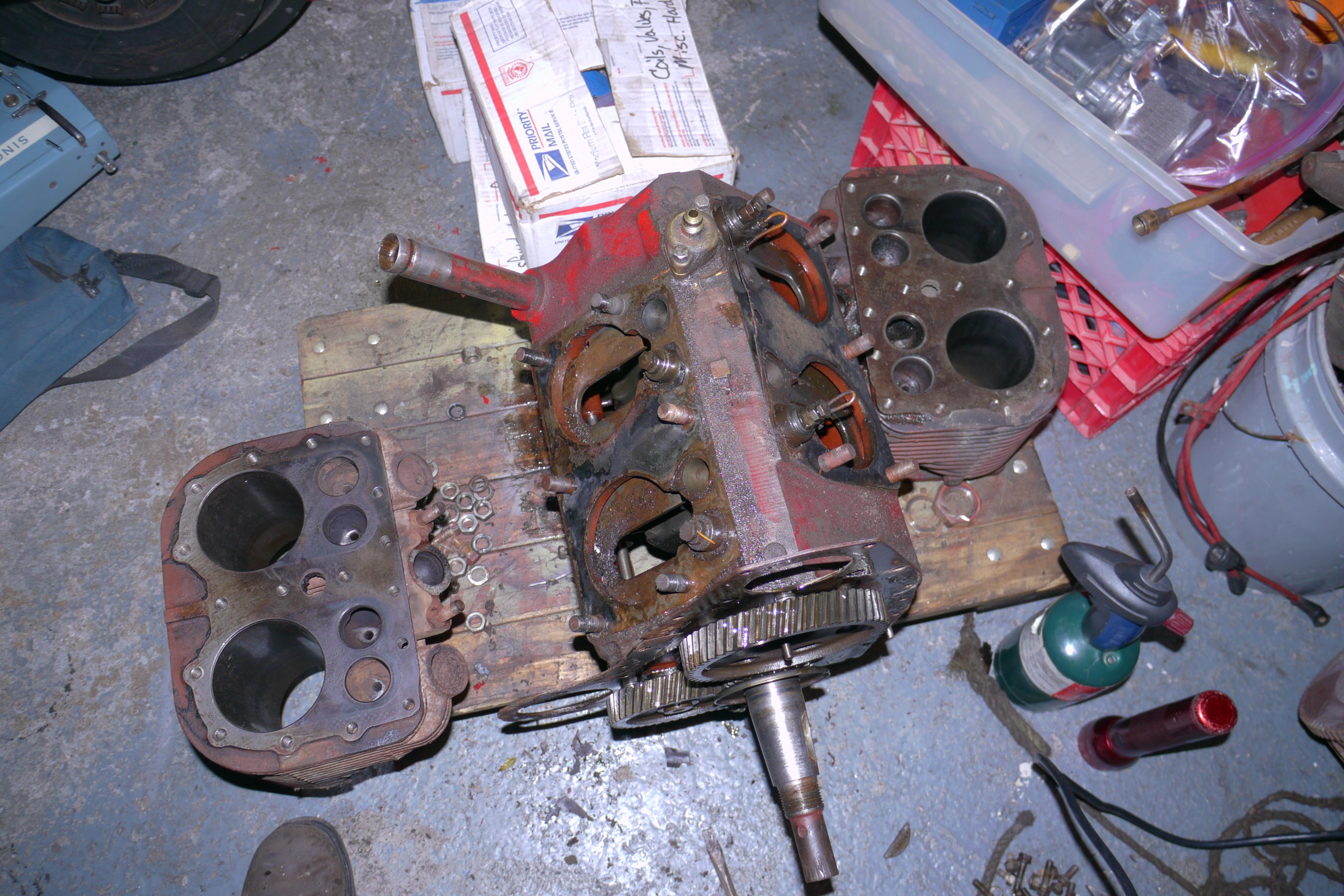
Wisconsin used this style piston before they adopted the cam-ground piston design in the 1970’s. There is nothing wrong with these pistons, they could have been bead blasted, ultrasonically cleaned and re-ringed, but I decided it was time to update the engine half of the compressor to the later cam-ground piston design. I had several brand new in the box, and decided to use those instead. Wisconsin offers two types of rings for their engines; Cast Iron rings and Tri-Crome rings. Tri-Crome ring sets were offered in the 1970s and were comprised of three chrome compression ring and a single cast iron oil control ring. The Tri-Crome ring sets worked good when re-ringing a piston in the field without boring and honing a cylinder to size. The chrome rings were inherently harder than the nickel iron cylinders and took an extremely long time to wear in and seal up. That is the big problem with tri-chrome rings, as they take hundreds of hours to break in rather than just a few hours. Owners would note that oil consumption was greater after a Tri-Crome rebuild, and often wrote the engine off without letting it actually wear in and work properly. The current ring sets from Wisconsin are the best of both worlds, including an upper chrome compression ring, two lower cast iron compression rings and a multiple piece oil control ring. There will be more on that later. First we have to remove the cylinder jugs from the crankcase! The compressor side cylinder is simple to remove as their is ample space between the blower shroud and the cylinder to remove the perimeter nuts that secure the cylinder to the crankcase. In order to remove the engine side cylinder jug, several components need to be removed; including the blower shroud, the flywheel, and the gear cover. The flywheel is not particularly easy to remove. The flywheel is held onto the end of the crankskaft by a large nut. The nut is often easy to remove. What makes pulling the flywheel difficult is the rust that builds up between the taper of the crankshaft and the tapered bore of the flywheel. I have pretty good luck heating the center of the flywheel up, and hitting the end of the crankshaft with a lump hammer. The shock after several hits is usually enough to pop the flywheel off its taper. With the flywheel removed, the blower shroud can be completely removed. This gives access to the bolts which secure the gear train cover to the front of the crankcase. Once this cover is removed, the flexplate can be wiggled enough that you can remove the perimeter nuts which hold the engine side cylinder to the crankcase.
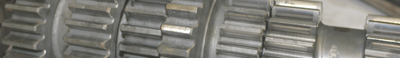
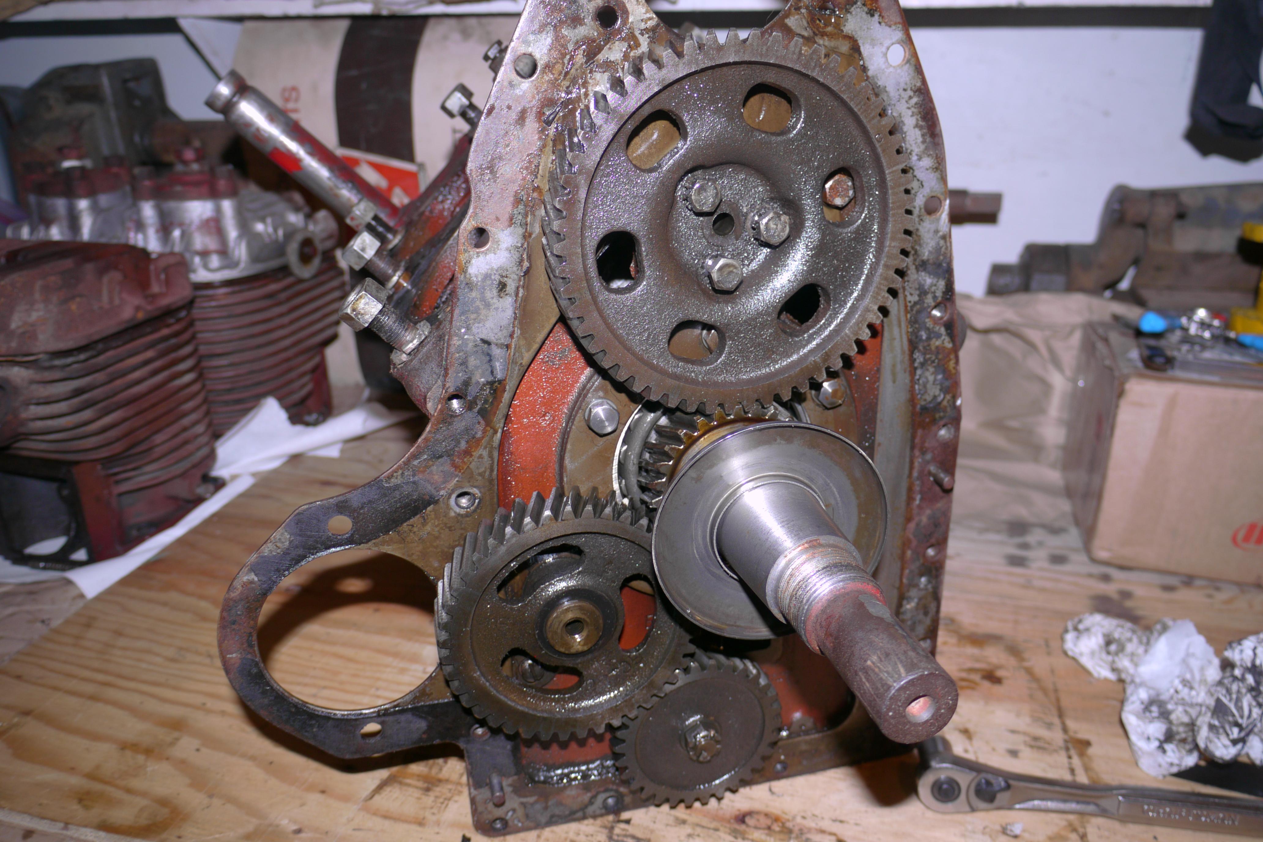
This engine uses diagonally cut spur gears to transfer power from the crankshaft to the camshaft, oil pump, governor and distributor. In order to proceed, you must carefully remove the oil slinger from the crankshaft. The slinger usually comes off without too much trouble. At this point you can remove the camshaft, which is retained by three bolts. It can be pried out of the crankcase without too much trouble as long as the valves are out of the engine. The lifters will simply fall out of place when the camshaft is removed. At this time, you can remove the crankshaft, which takes a little finagling to remove. It can only be fit into the engine one way. Sometimes you need to pull the PTO side bearing race so that the crankshaft can come out the rear of the engine. This is the method I used. Once removed you can see the oil baffles above the crankshaft which prevents too much oil from being splashed on the bottom of the pistons. By now you can see how much dirt and debris is inside of the engine. That will all need to be flushed out before its time to rebuild the engine. Now that the engine is essentially pulled completely apart its time to start cleaning the parts up. I am very particular about the way my engines work and run. I like every part to be perfectly clean and machined before it all goes back together.
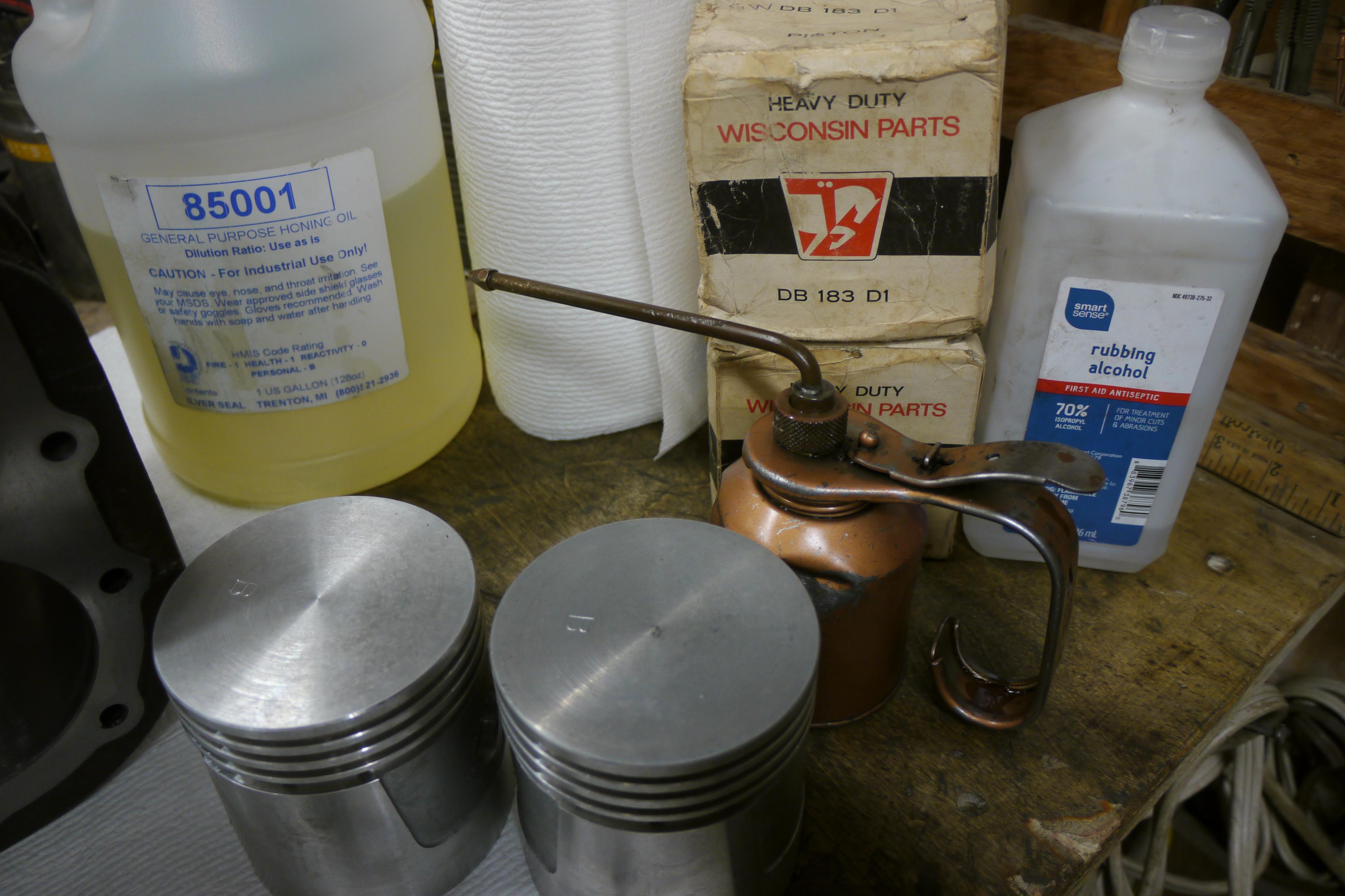
Prior to this purchase I spent a lot of time setting up an industrial air compressor to run my Trinco blasting cabinet. I prefer to de-grease all of my parts before sandblasting them with Clemco Zero 801210 glass beads. With the size compressor I have, sandblasting is quick and efficient.
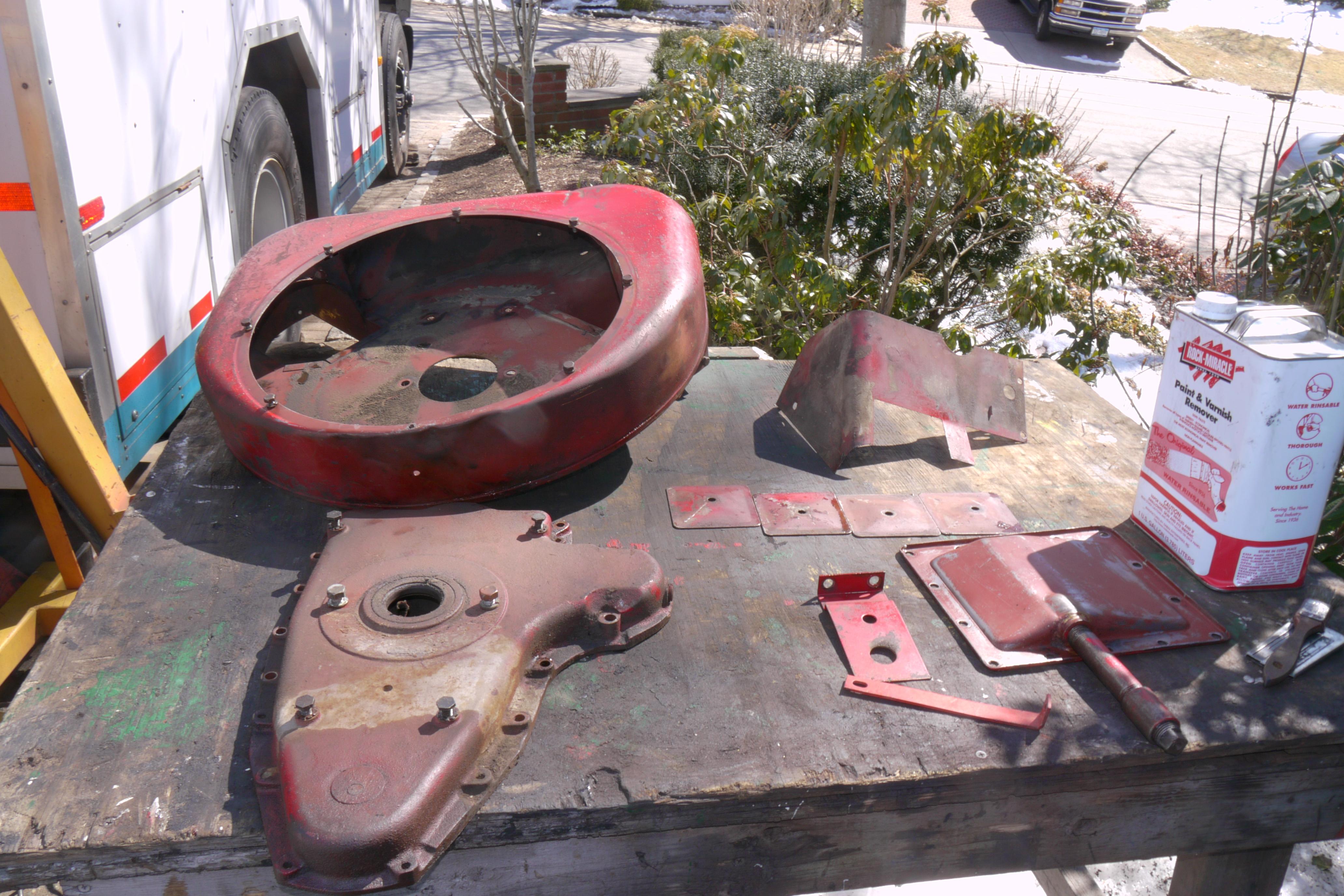
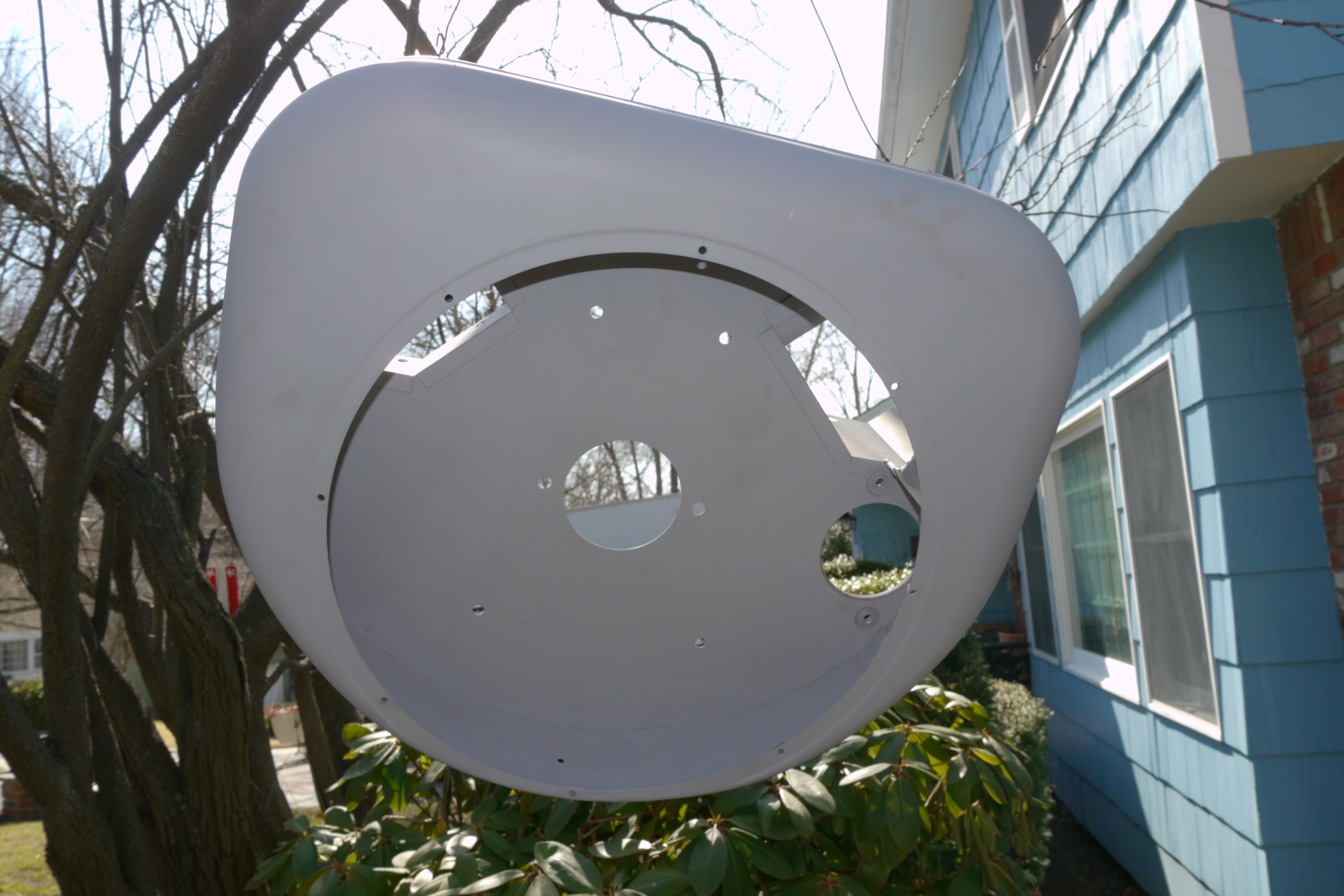
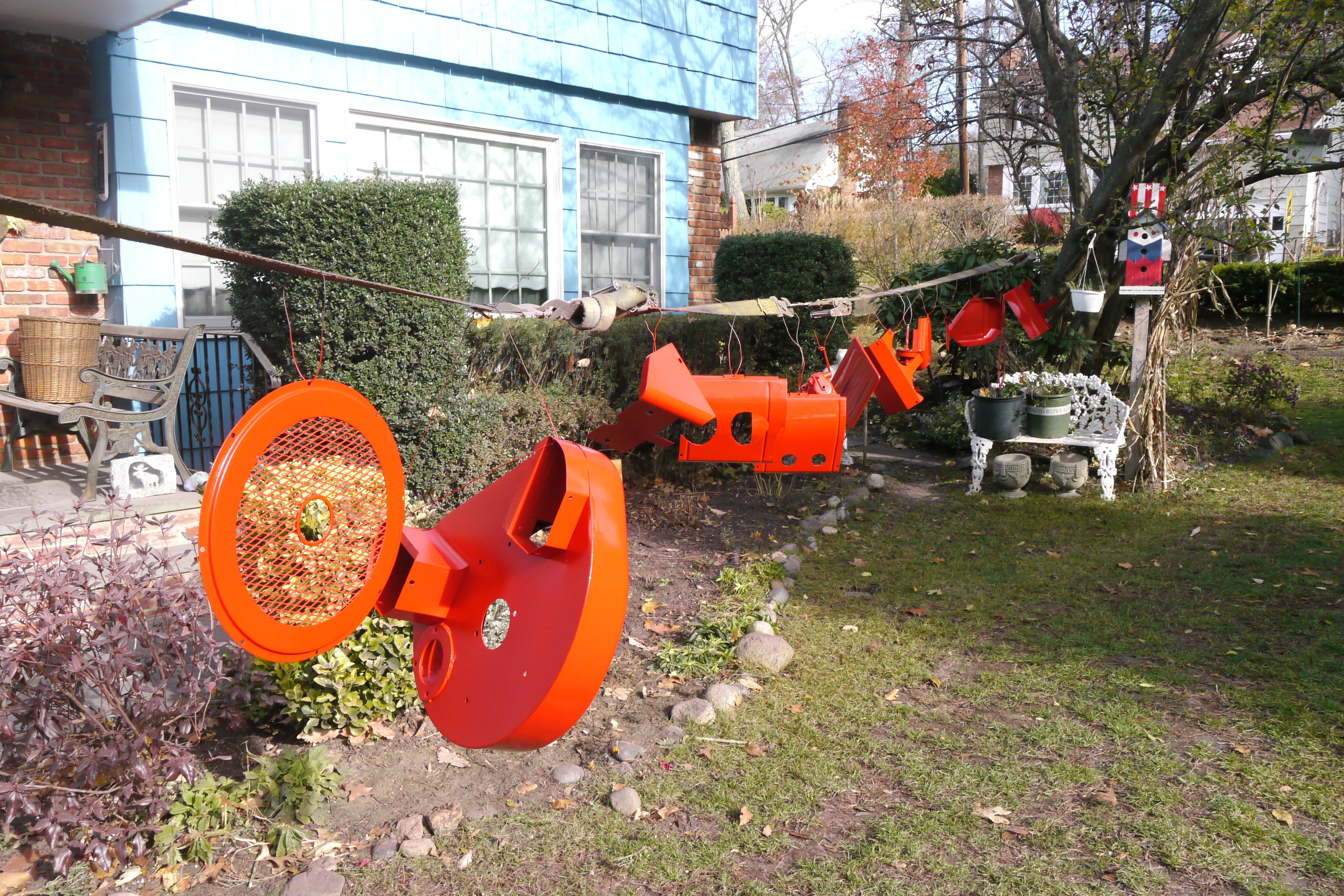
I prefer to use Rock Miracle paint stripper to remove stubborn paint. It works fast and is very strong. Heavy rubber gloves, chemical safety goggles and a respirator are a good idea when using this product. I started by liberally applying the paint stripper to the blower shrouding and various sheet metal pieces which duct air around the engine.
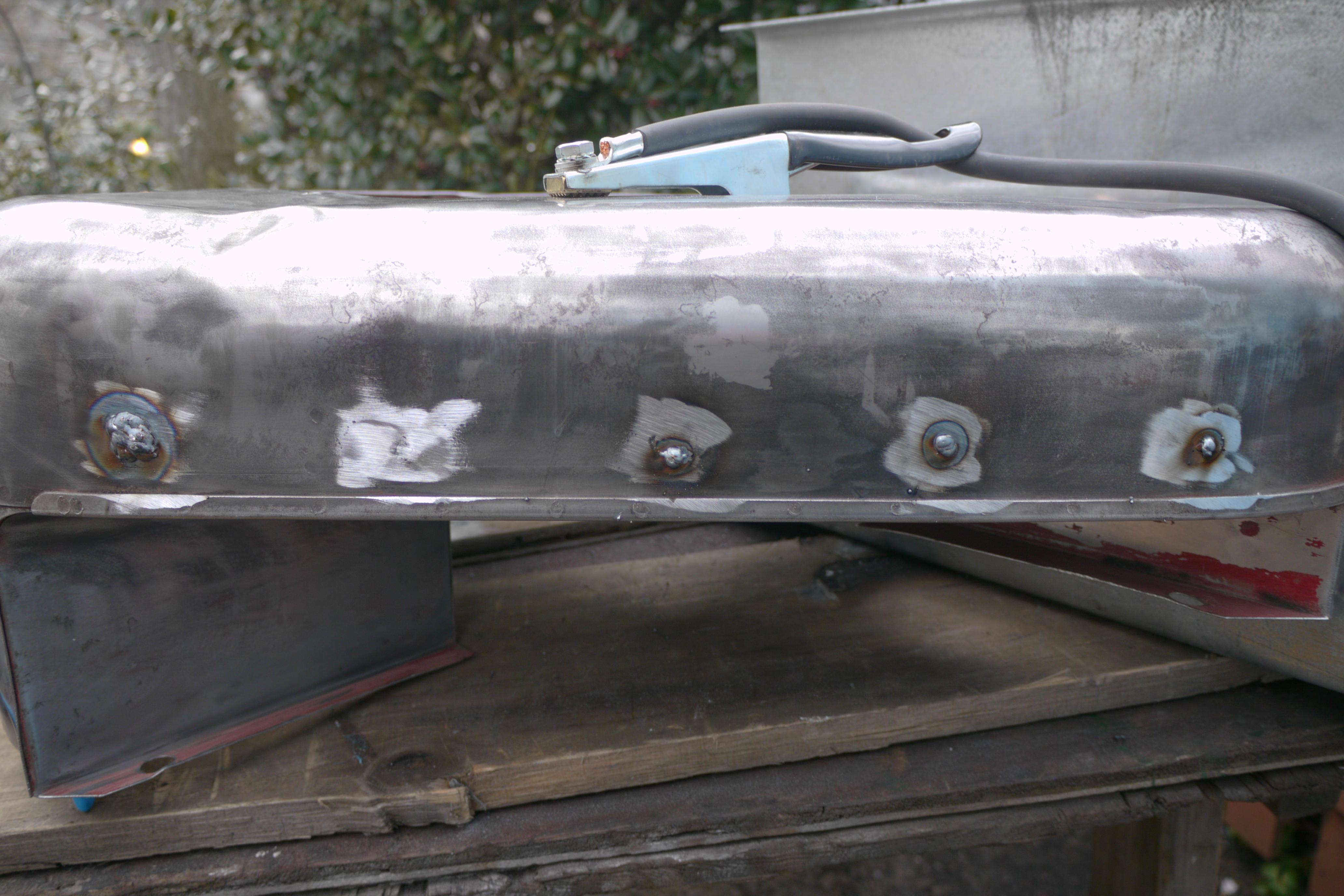
Once the majority of the paint was stripped I spent some time filling small holes in the sheet metal with my welder. Welding thin sheet metal is particularly difficult. Its best to start with thin wire on a low heat setting. If you start building up weld on known good material it will be easier to pull weld into the hole than it would be to build up the hole from one side to the other. Once all of the holes were filled, I used the flap-wheel on my angle grinder to smooth the weld out until the hole disappeared without a trace. I spent a lot of time with metal shaping hammers to pound out some of the big dents in the blower housing. It is important that the blower shroud be complete and uniform in section. If any dents impede air flow it will be noticeable later on with higher than normal engine operating temperatures.
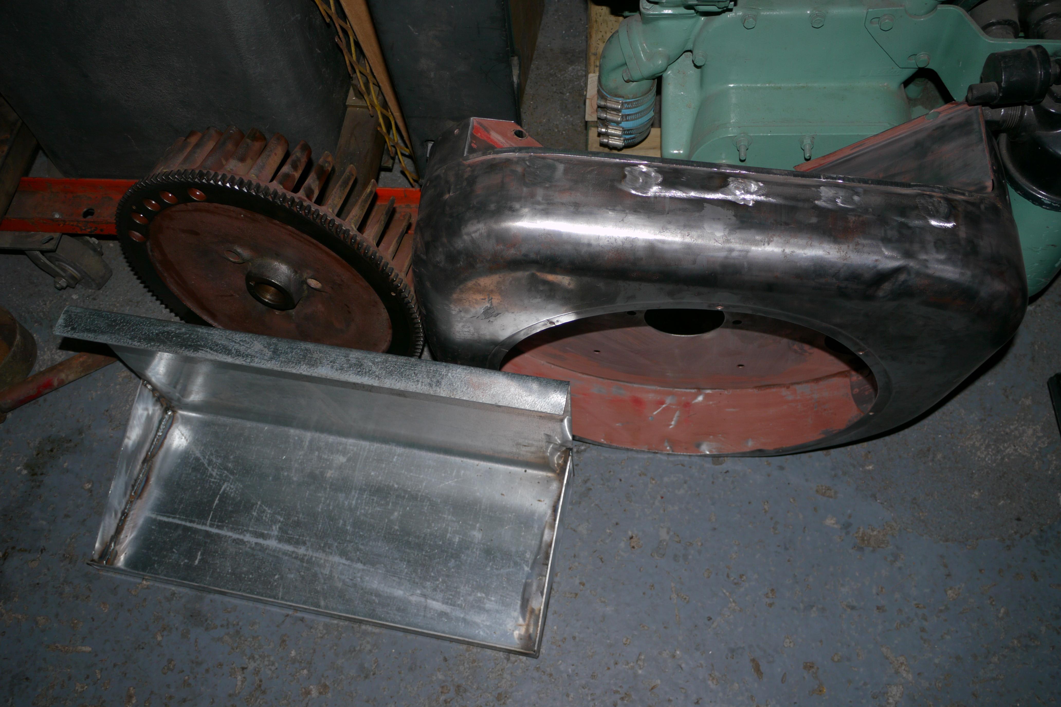
I use a number of methods to remove dents. Welding studs and using a slide-hammer is one of the best methods to pull out dents from thicker metal. On thinner metal you can sometimes heat the surface and run a large steel bearing on one side with a neodymium magnet on the other. Using filler is a last method resort. I like to fix things right the first time, and only use filler materials to ensure a nice smooth surface. A lot of folks use bondo, but I do not. For how little body filler I usually need, I use Jbweld 8280 industrial two part epoxy. I prefer Jbweld because it bonds to metal really well and sands really nicely with a block sander/orbital sander.
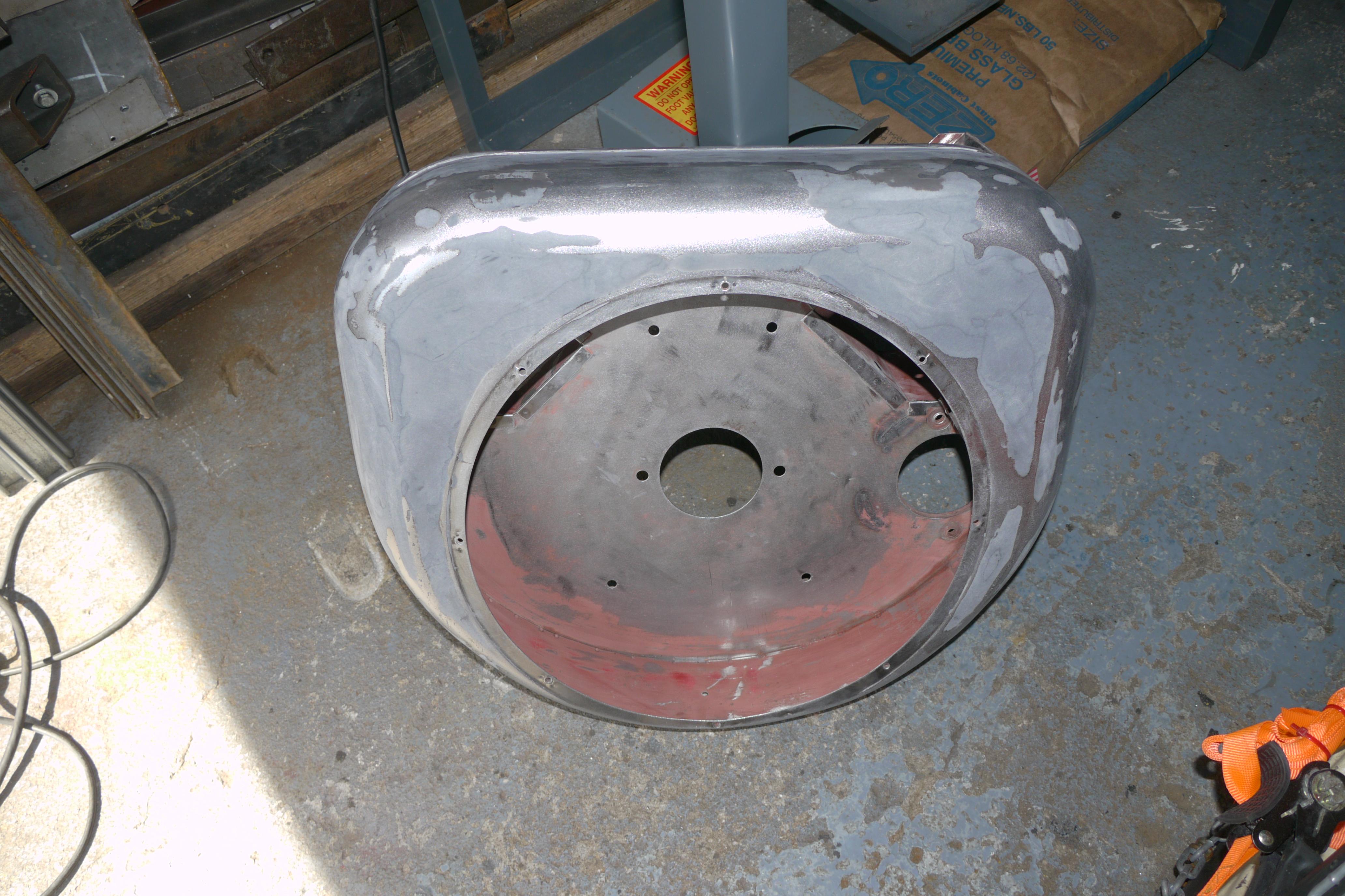
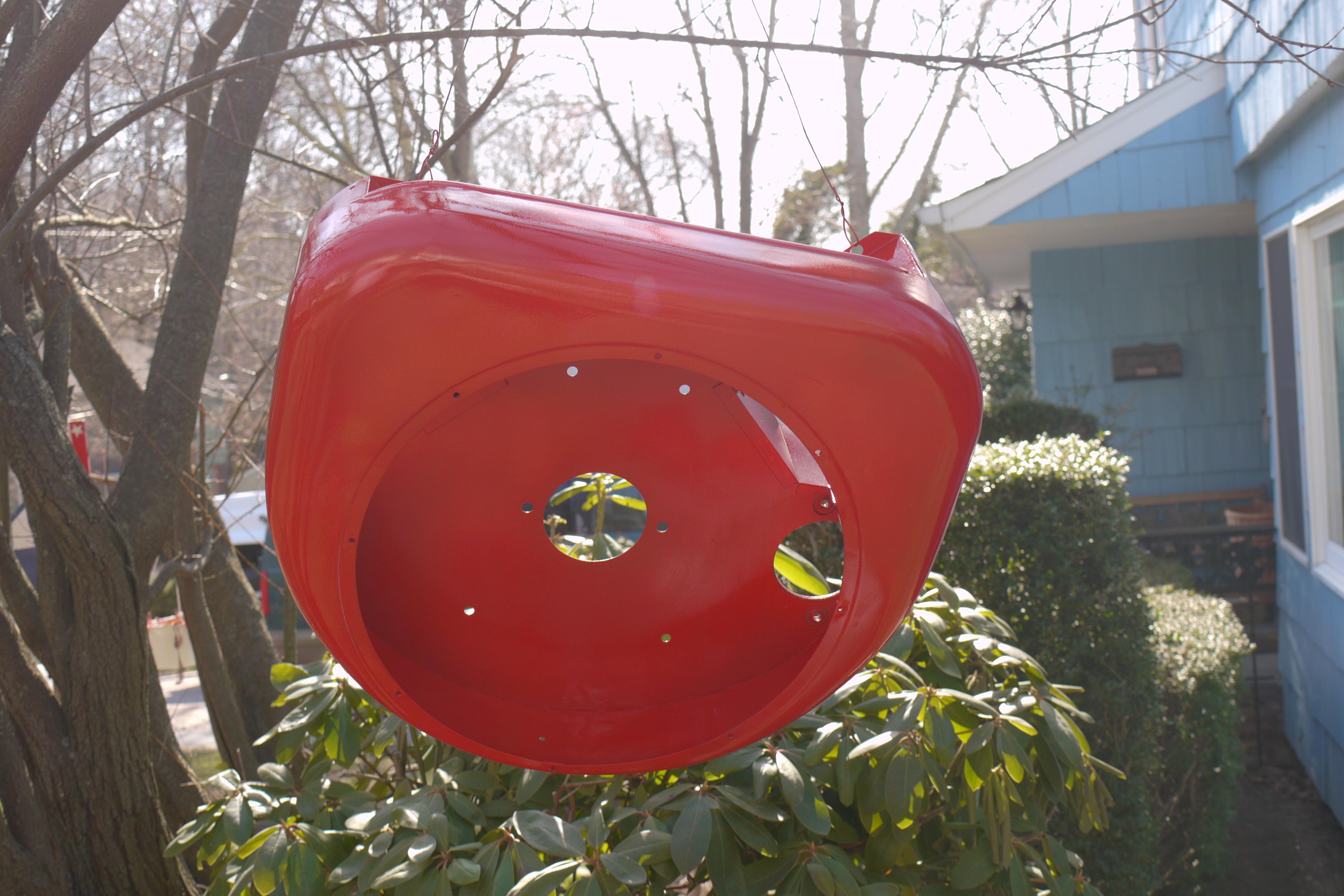
Once I am happy with the surface finish I like to coat my parts with industrial primer. Only after it is thoroughly dry do I apply a top coat. In this case I used three coats of an industrial enamel paint that holds up well against gasoline and fuel oils. Painting is so nice because it provides instant gratification.
While the paint was drying, I spent some time porting and polishing the intake and exhaust ports in both the engine and compressor side cylinder jugs. This is normally only done on high performance engines, but the way that Wisconsin cast their cylinders leaves a lot to be desired in regards to the flow of intake and exhaust gasses. The point of porting and polishing the intake and exhaust ports is to remove any irregularities from casting, and to help the engine breathe better. The smooth surface reduces friction between the air/fuel mixture and the cast iron ports preventing the gas fuel mixture from condensing on rough castings. In air cooled engines, breathing is everything to successful long life engines. If you can open the ports just 10% in overall volume you can nearly double the volumetric efficiency of the engine. Air cooled engines operate at nearly three times the temperature as water cooled engines. It is uncommon to see 450-550*F temperatures on the cylinder jugs and as much as 850*F on the exhaust manifolds. If you can reduce the time that it takes for the exhaust to exit the engine, the less heat that can radiate back into the engine through conduction.
That being said, it is important to match the enlarged ports on the exhaust manifold side of the port. There is no sense porting and polishing an engines exhaust ports if you do not carry out the same procedure to the manifolds that fasten to it. If Wisconsin engines had any flaws it was there cast iron exhaust manifold design. The exhaust manifolds were fastened to the cylinder jug with special rolled washers. The way they fit them to the engine was such that the exhaust manifold and intake manifold shared the same fasteners. The heat from the exhaust causes the exhaust manifold to expand, while the exothermic reaction of carbureting fuel cools the intake manifold, resulting in a huge temperature differential which cast iron cannot withstand. As a result the cast iron exhaust manifolds are known to crack at the bases. My two compressors are no exception and have cracked manifolds. After porting and polishing the broken exhaust manifolds I spent some time sandblasting them. One of the keys to welding cast iron is that the surfaces need to be extremely clean. The hardest part about welding exhaust manifolds is that they have become contaminated with carbon and hydrogen embrittlement during normal operation. Once prepped for welding, the manifolds need to be brought up to temperature to prevent stress risers from forming in the brittle casting. I like to bring the temperature of the cast iron part I plan to weld up to at least 500*F so that welding does not "shock" the metal too much. I have personally found that shot-peening the casting hot helps tremendously between cycles of welding. You cannot weld cast iron too much at one time, or else it will begin to crack. So far I have been successful welding cast iron up with just my Miller 252 welding machine and standard welding wire. Once welded, the part has to cool extremely slowly to avoid cracking. I typically use a propane torch to keep the part for an extended period of time after welding to keep the part hot enough that it internally recrystallizes. After post heating, I wrapped the manifold in heavy wool matting which contained the heat around the part. At the end of the day the part has finally cooled enough to handle. At this time, I check that none of the corrected cracks have propogated. Once repaired, I brought the manifold over to my large belt sander to smooth the base of the manifold so that it could be fitted back to the engine nicely. It is amazing how much the manifolds warp on these engines.
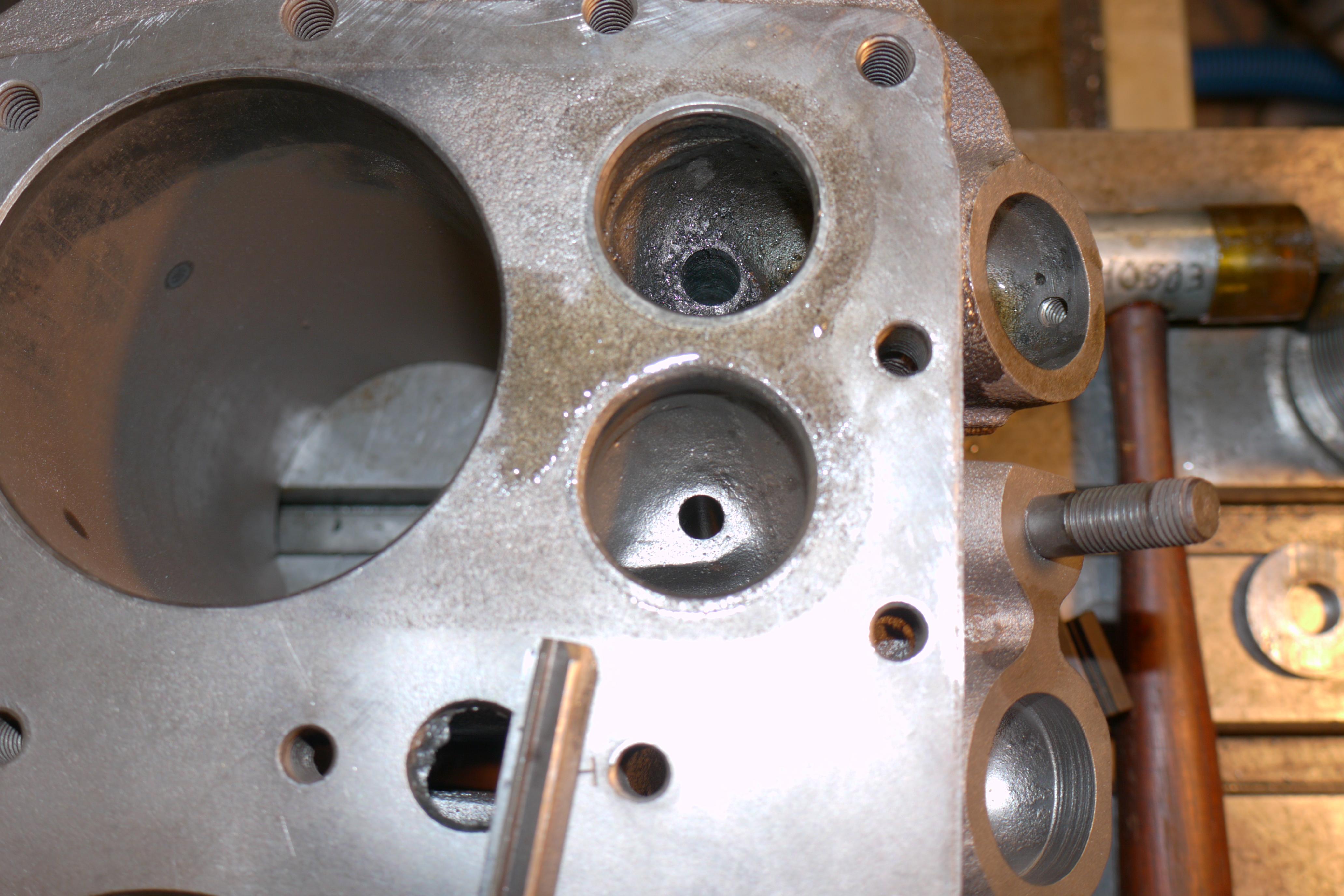
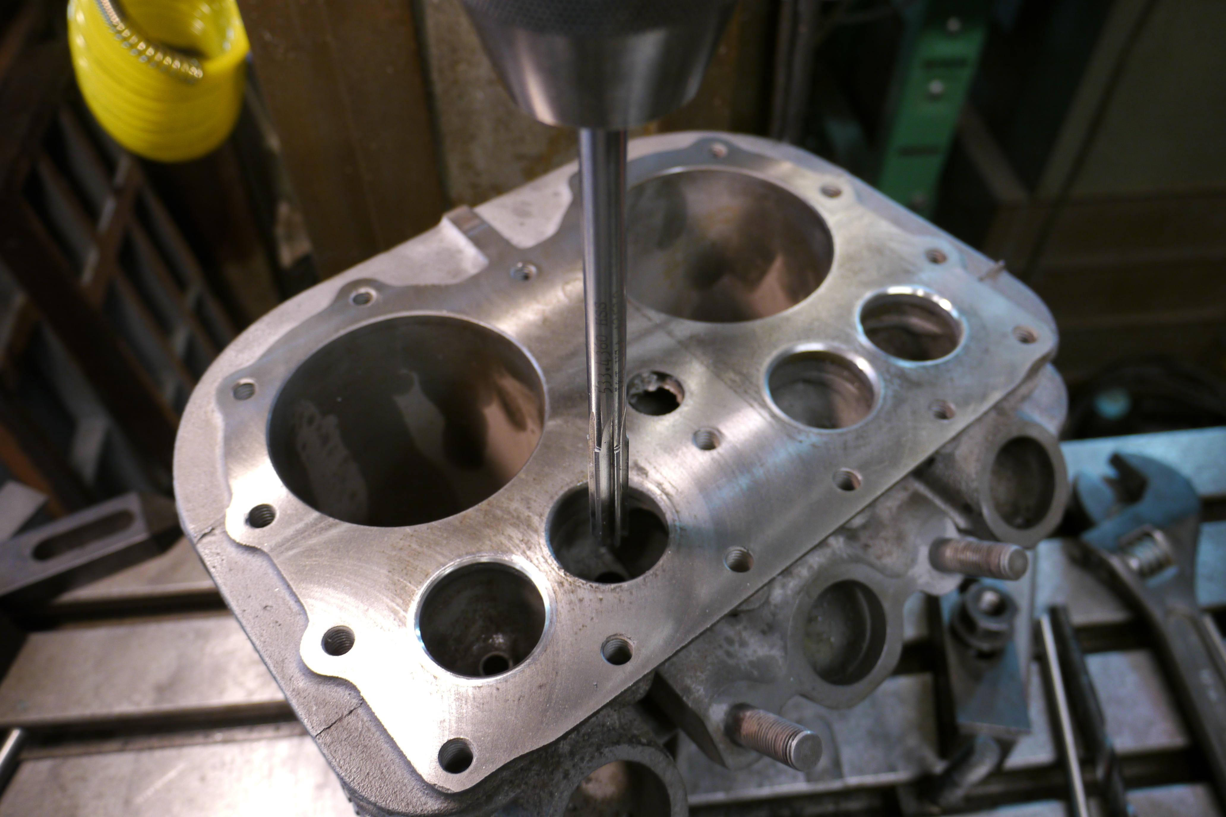
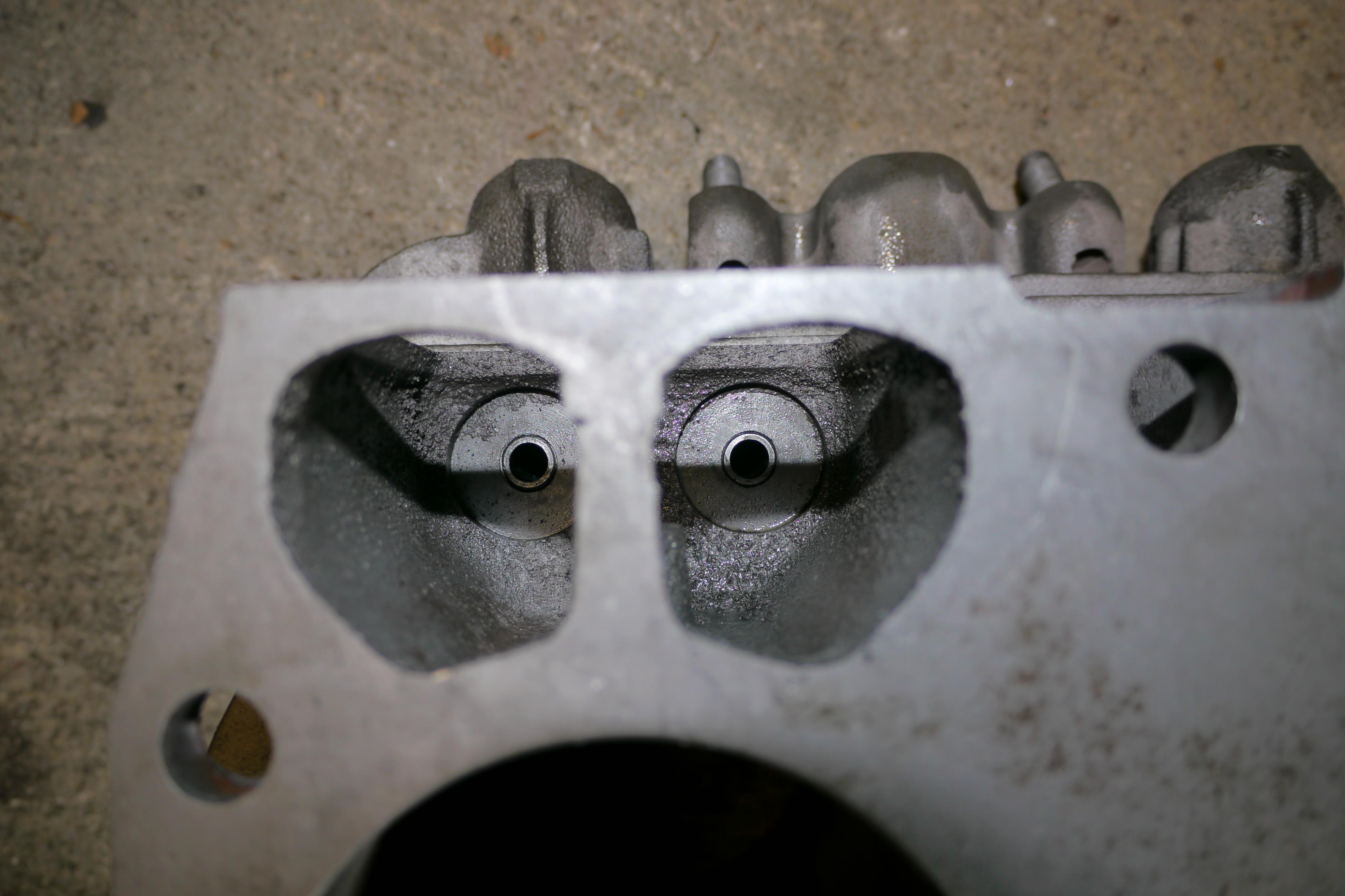
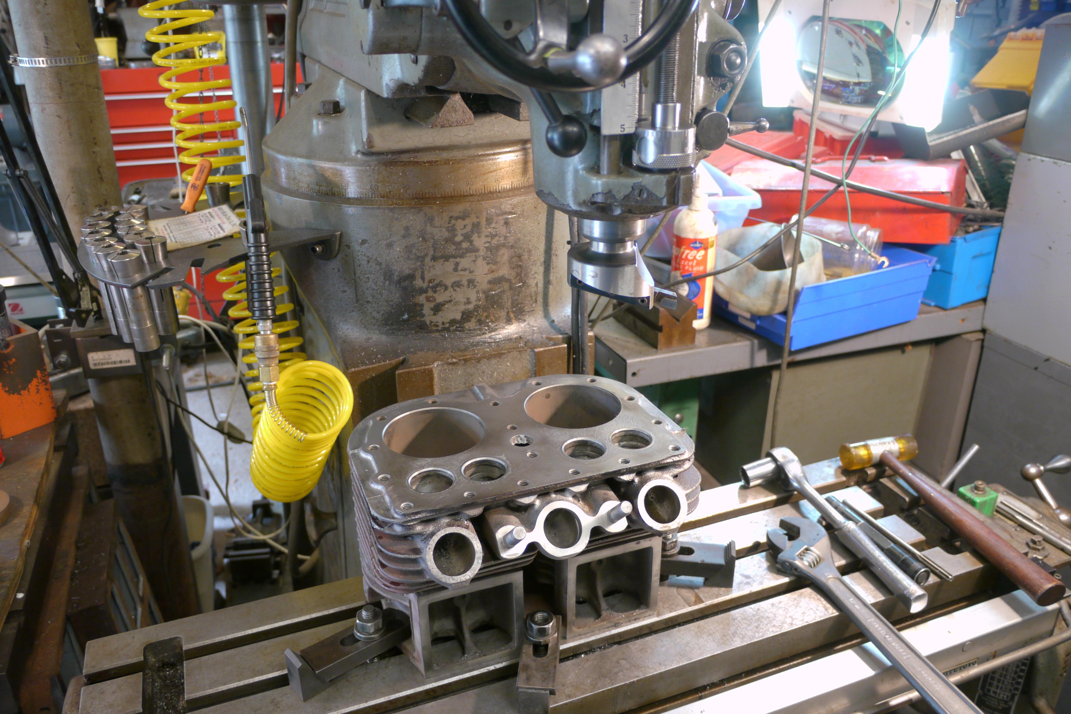
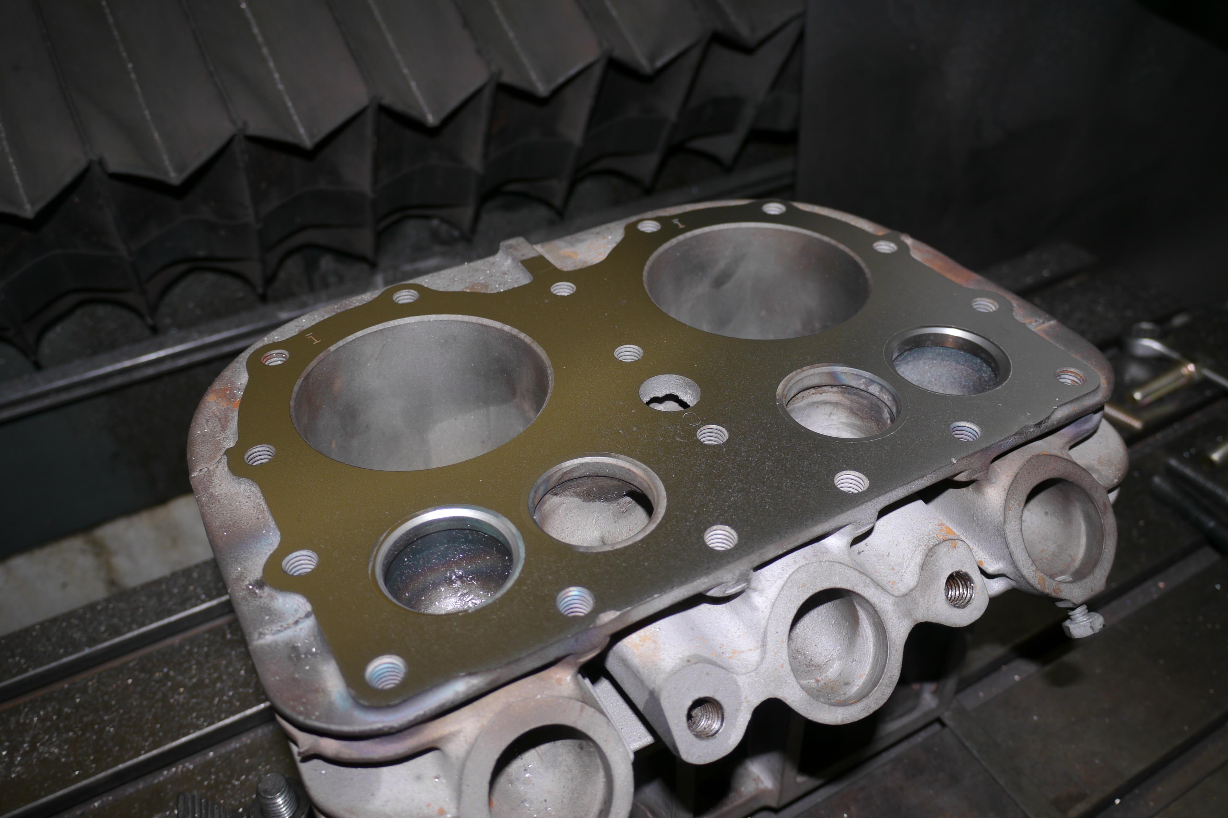
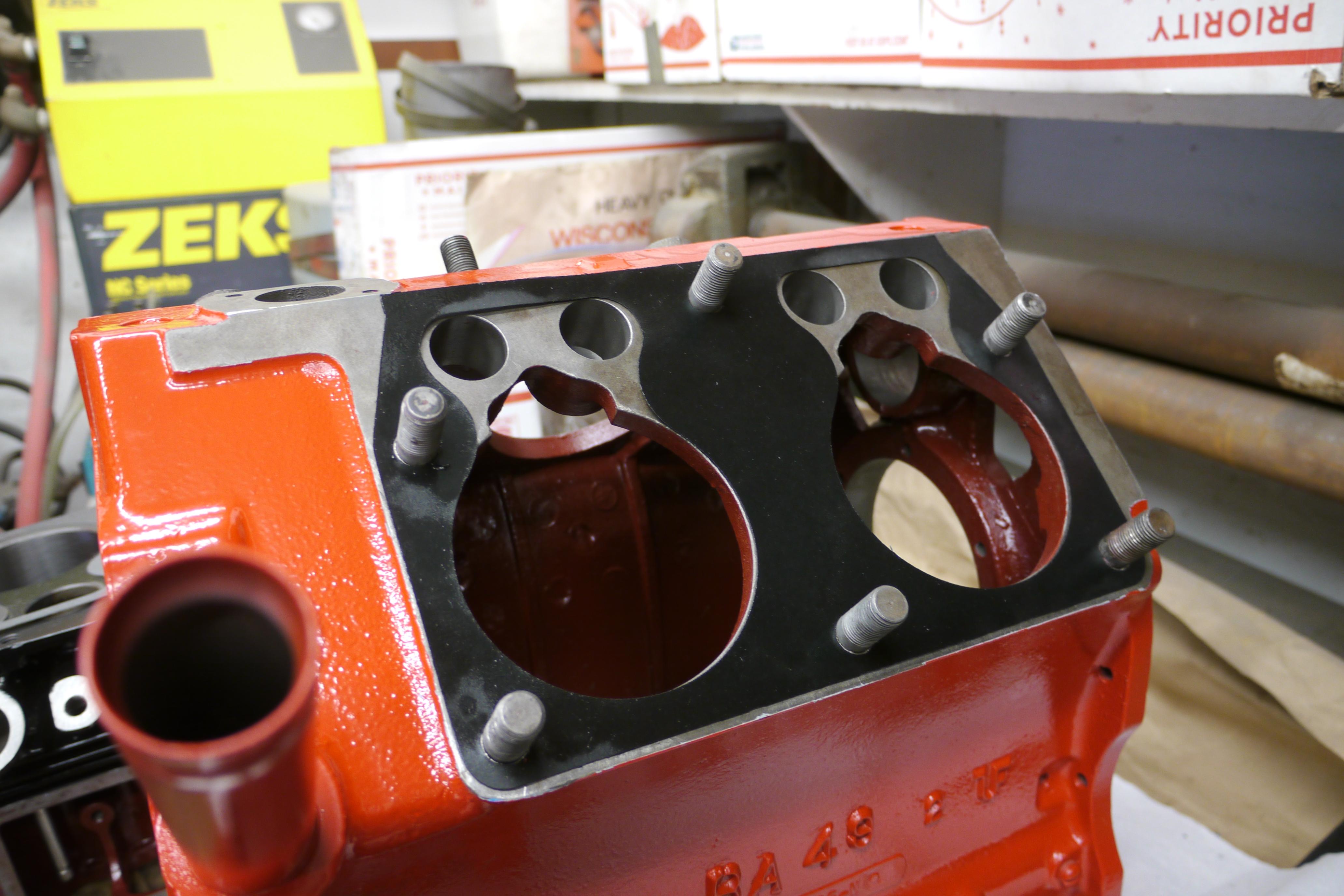
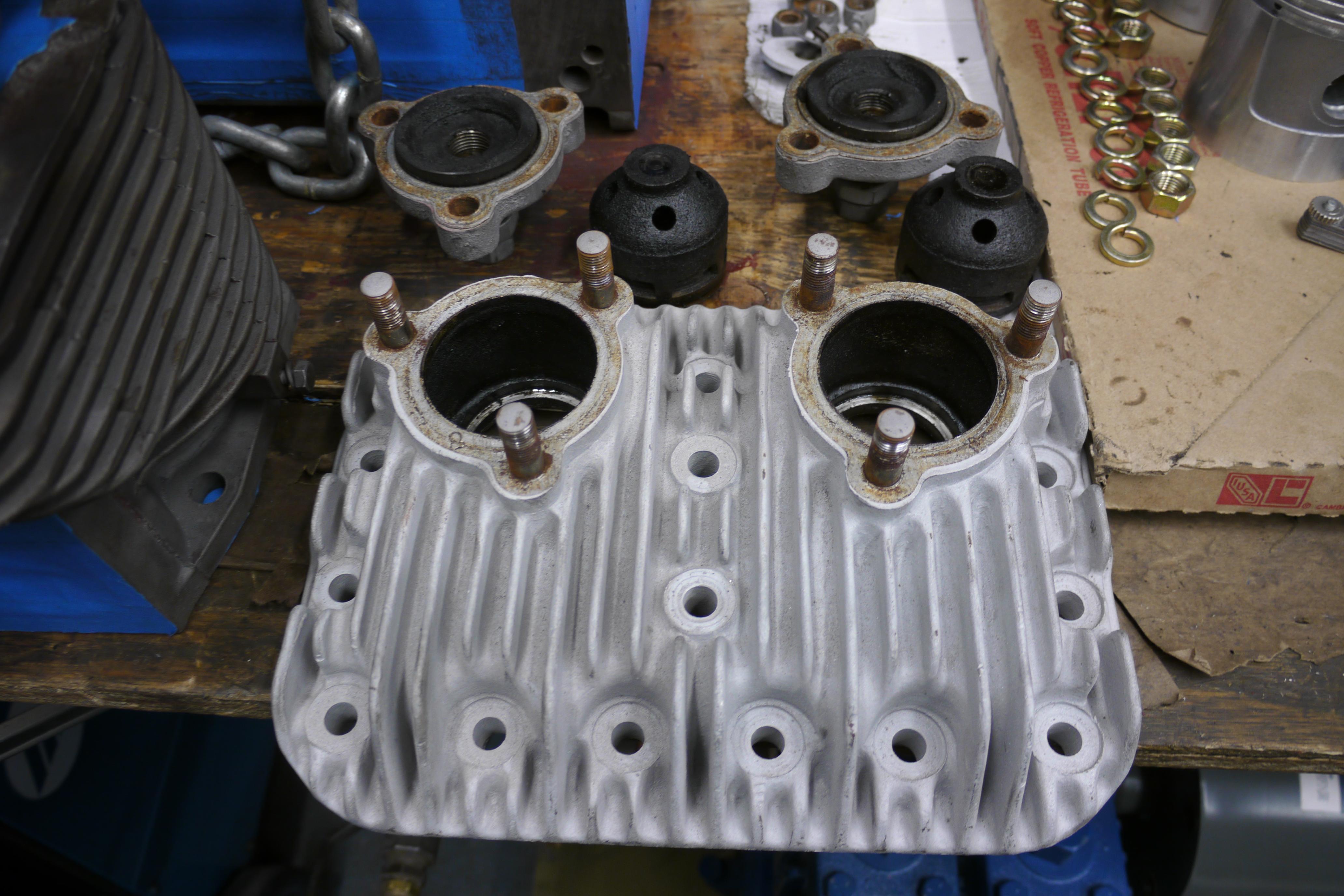
With the manifolds fixed it was time to work on the heart of the engine, the engine side cylinder jug. After cleaning up the intake and exhaust ports, it was time to address some greater concerns: worn valve guides and a pitted cylinder deck. This particular engine was built at a time when Wisconsin was not yet using replaceable valve guides. In an air cooled engine it is very common for the valves to super-heat and gall up inside of the valve guides. There was some slop in the current valve guides that I wanted to clean up. In order to do so, I had to setup the cylinder jug on the milling machine. Before mounting the cylinder jug to the table, I took a dull file to the underside of the cylinder jug and knocked off the corners and light scale until the blanchard ground finish was uniform across the base. I indicated the top of the cylinder jug in all directions and clamped the cylinder down when everything laid flat.
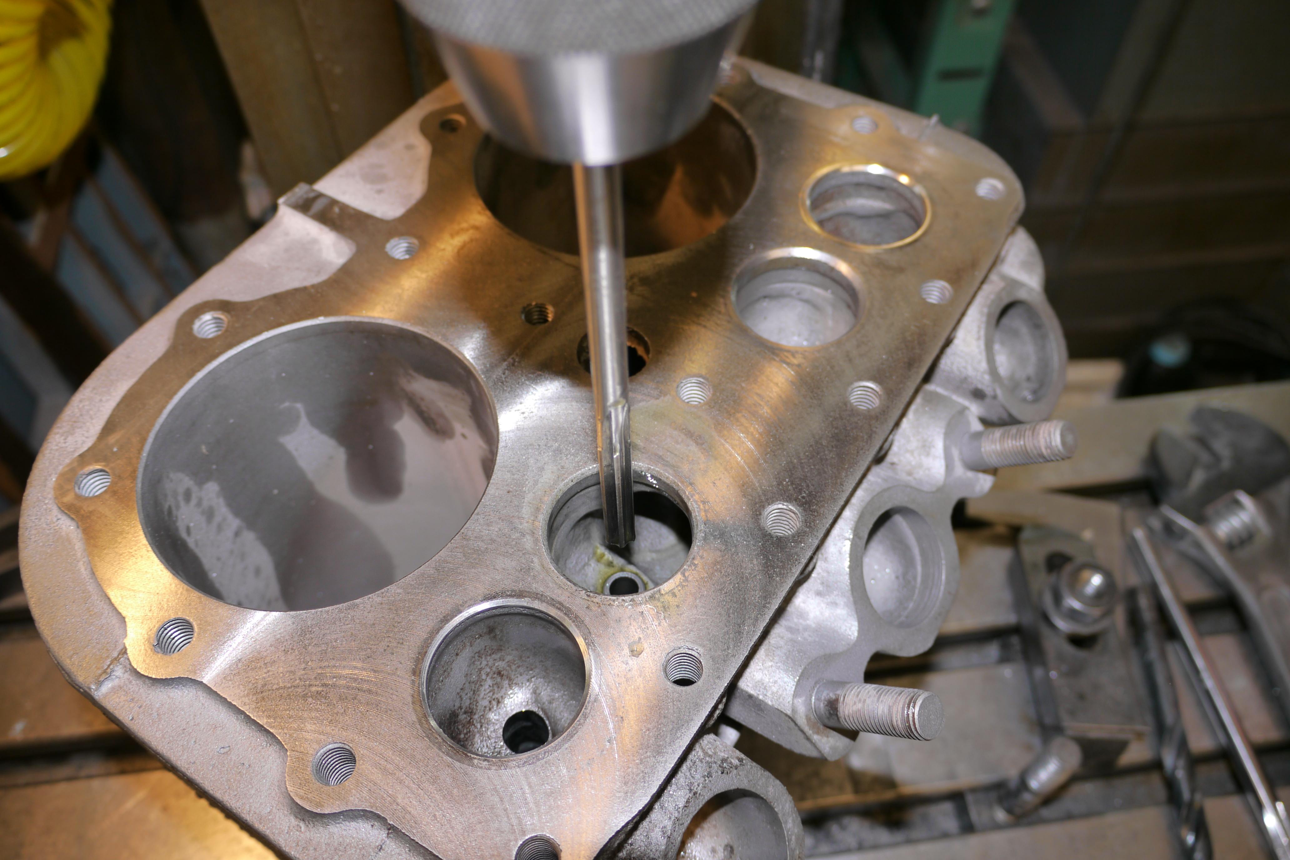
After indicating the top deck of the cylinder jug, I used an edge finder off the existing valve seats to find the exact center of the valve guide. Because the new AD-42 valve guides are much larger in diameter than the existing guide hole cast into the cylinder jug, a drilling procedure is necessary to enlarge the hole. Before any drilling can be done, it is good practice to make sure that head of your milling machine is in tram. Once in tram, and the center of the valve guide is found, the valve guide can be drilled out just shy of the final finished size. The new AD-42 valve guides were 0.438-0.439” in diameter, which necessitated the use of a 27/64” (0.422”) drill bit and a 0.4360” straight cut reamer.
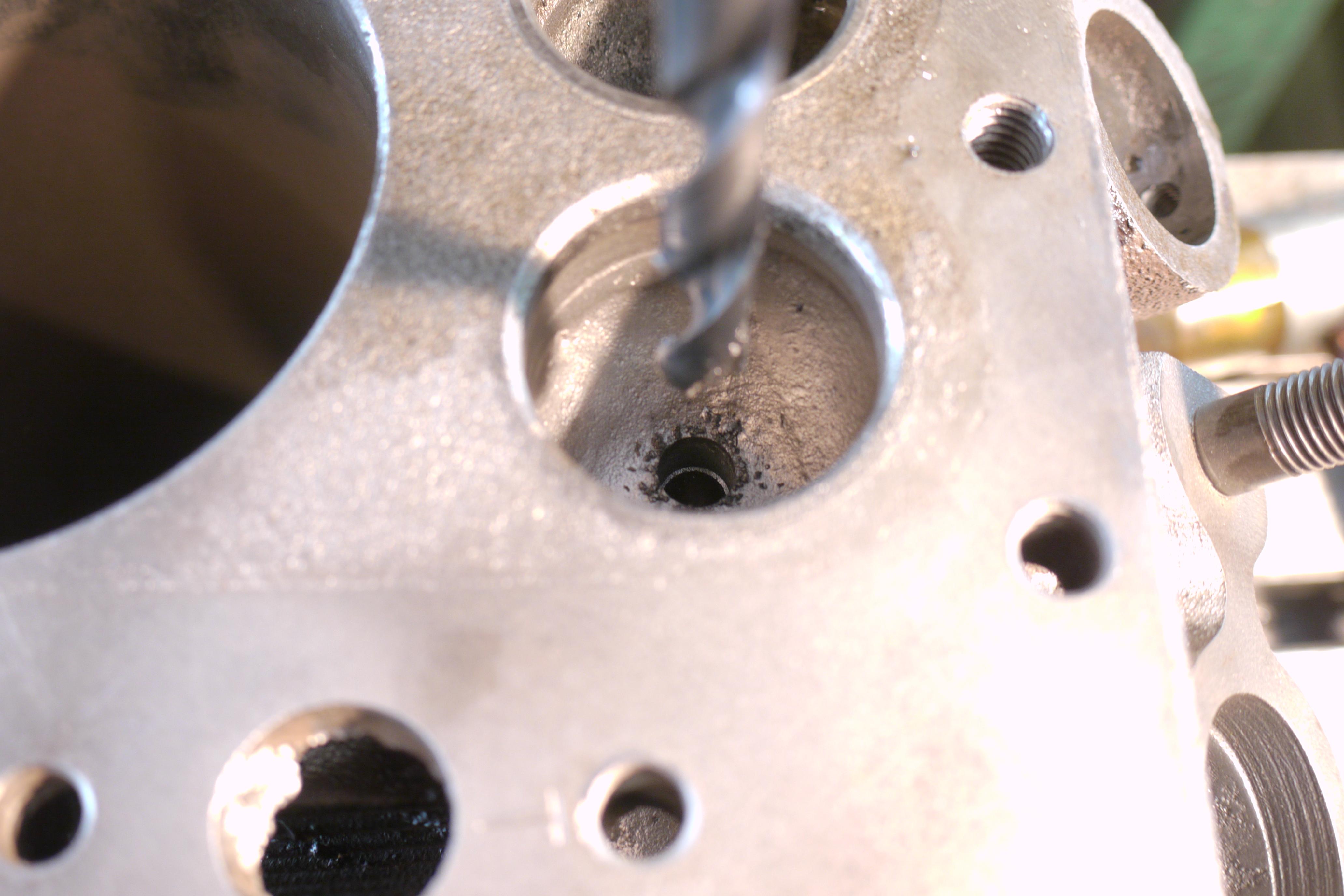
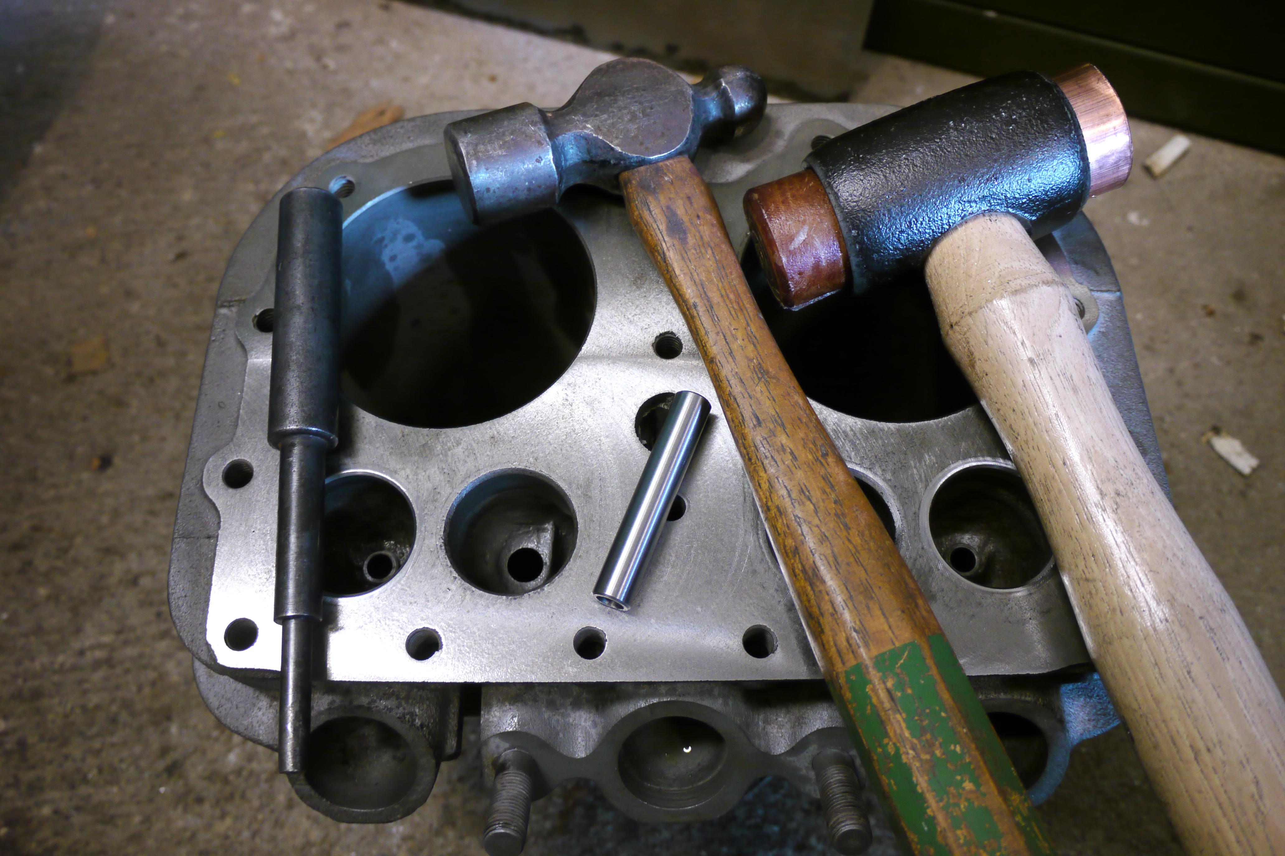
The reason the reamer is slightly smaller than the outer diameter of the valve guide is to provide a good interference fit between the cylinder jug and the new replaceable valve guides. Typically 0.0015-0.002” is the allowable interference fit for valve guides. Once the valve guide reliefs are machined to size, it is time to install the new valve guides. I used a stepped punch I had from another project.
The valve guides went in without too much trouble. I like to set the bottom of the valve guide flush with the ceiling of the valve spring pocket. At this point, the top of the guide sits nearly flush with the floor of the valve port. Because the valve stems are 0.308-0.309” in diameter and Wisconsin recommends a valve stem/valve guide clearance of 0.003-0.005”, it is necessary to ream the center of the valve guide to 0.3120” so there is proper clearance around the valve stem. The valve guides from the factory come with a 0.313-0.314” inside diameter, which is usually sufficient, but after the valve guide is pressed into the cylinder jug the new guide is slightly squished. It is good practice to run a reamer of the finished size down the valve guide. The 0.3120” reamers did not remove much material, but they ensured that the center of the guide was good, true and straight from top to bottom.
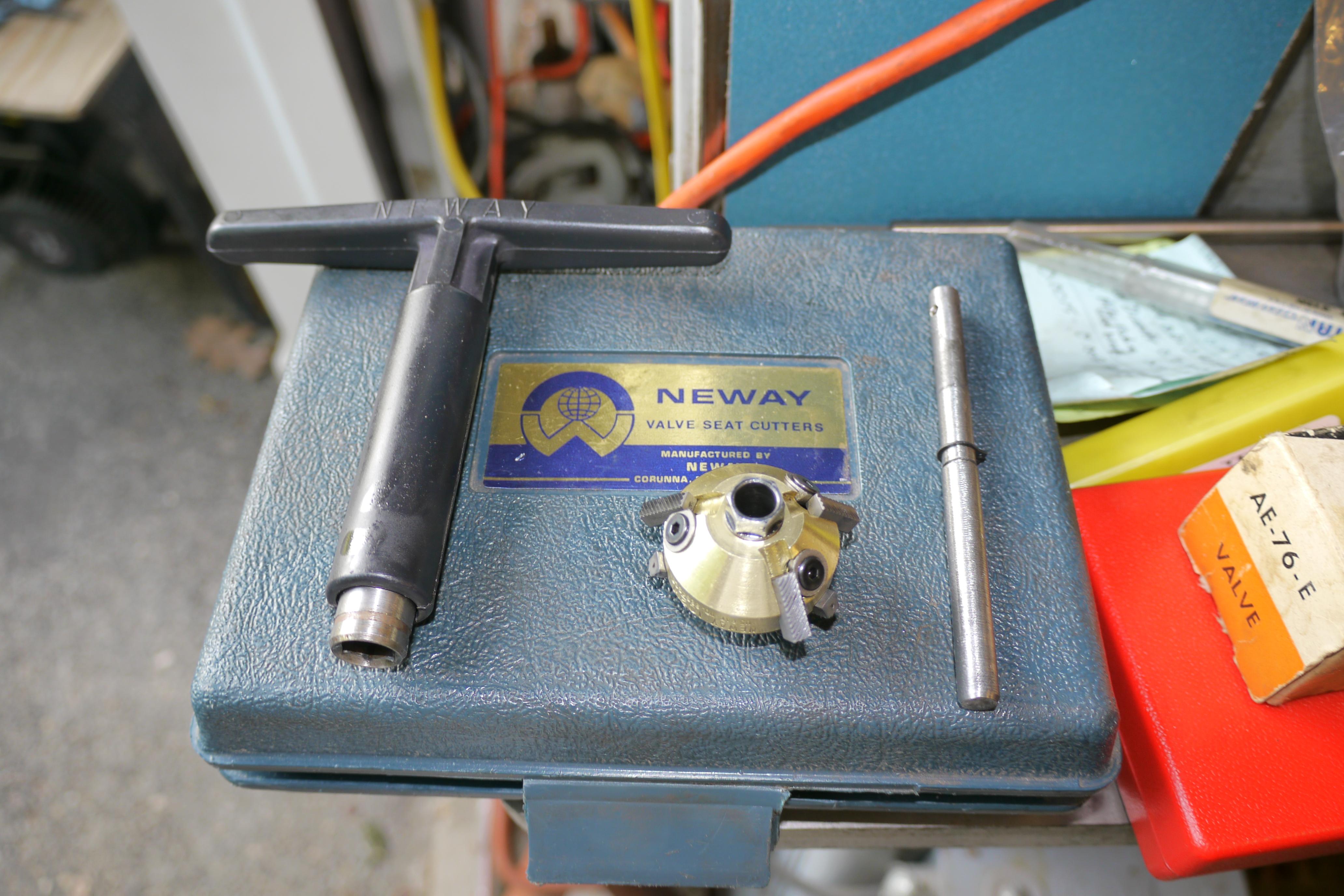
With the new valve guides installed and reamed, I fit my Neway valve seat cutter and attempted to cut new valve seats based on the pilot which fits into the valve guide. I was not happy with the way the valve seats looked and decided that it was time to remove them and install new stellite hardened valve seats.
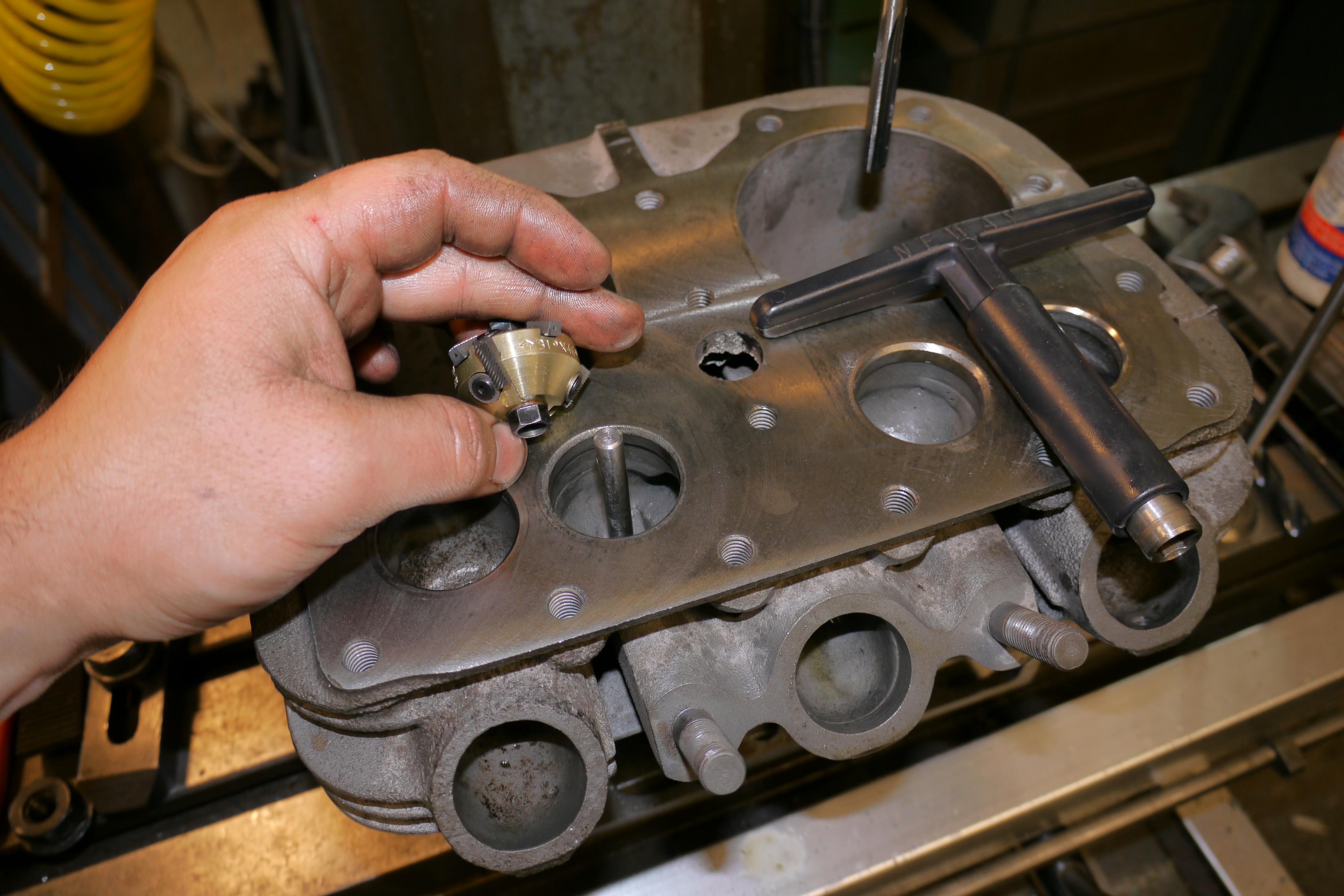
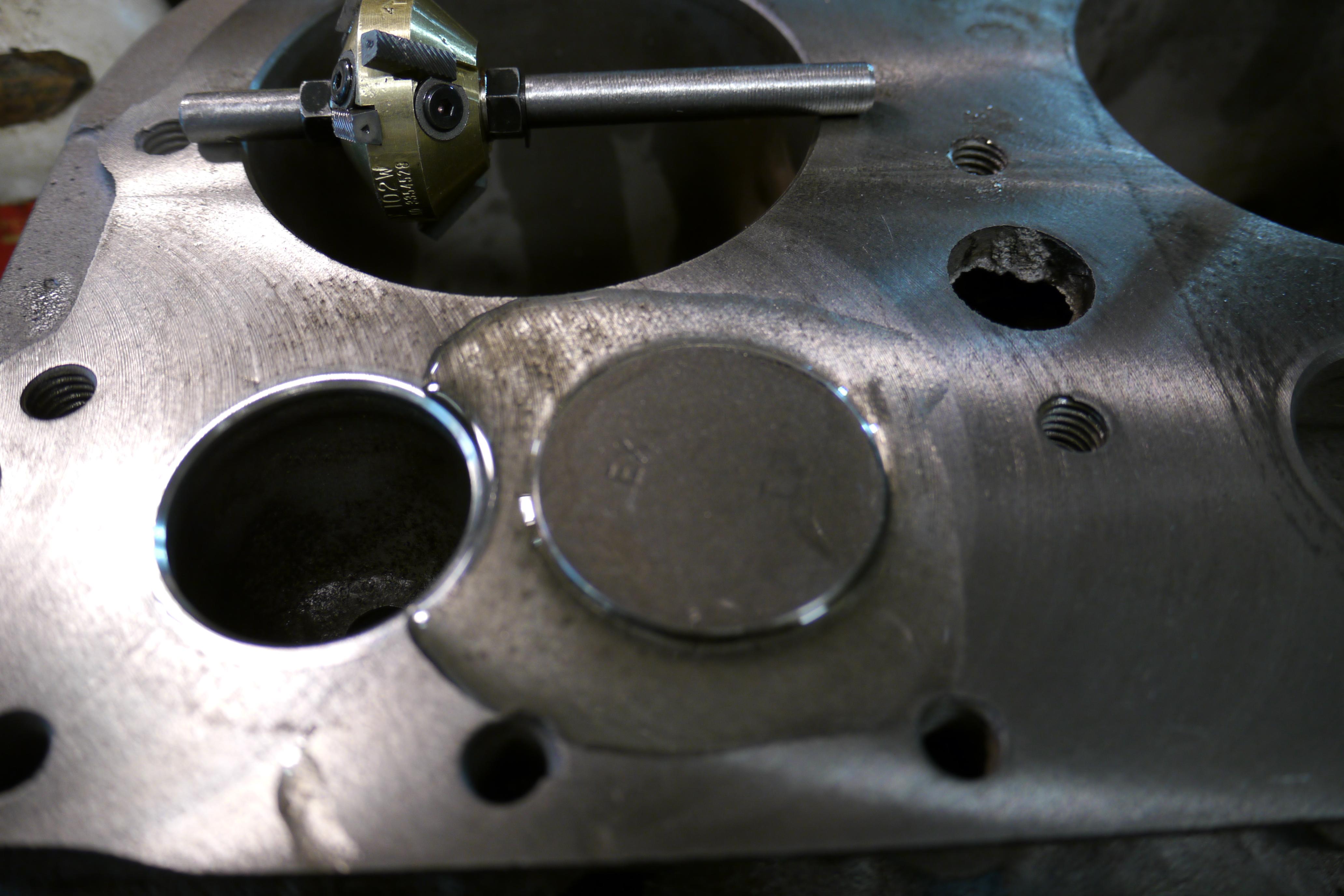
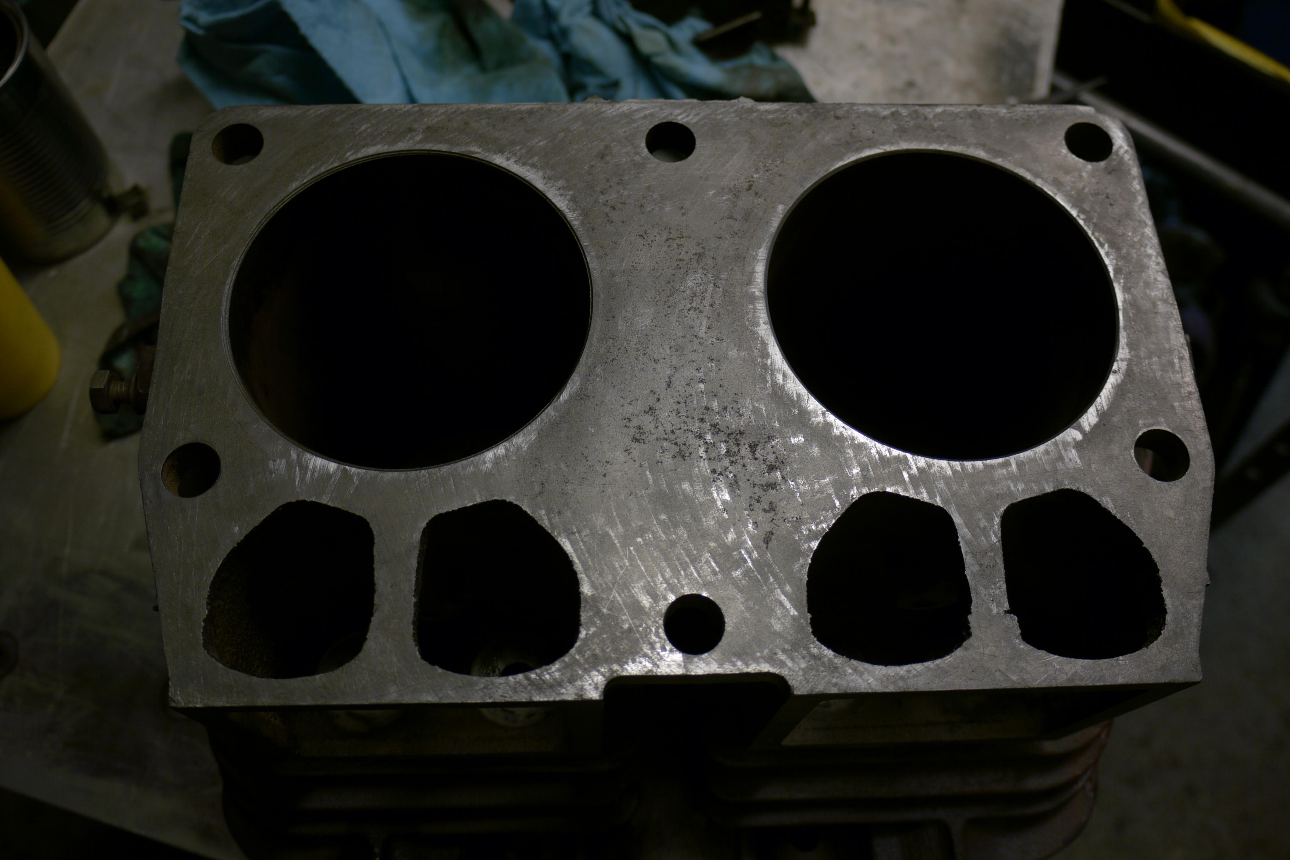
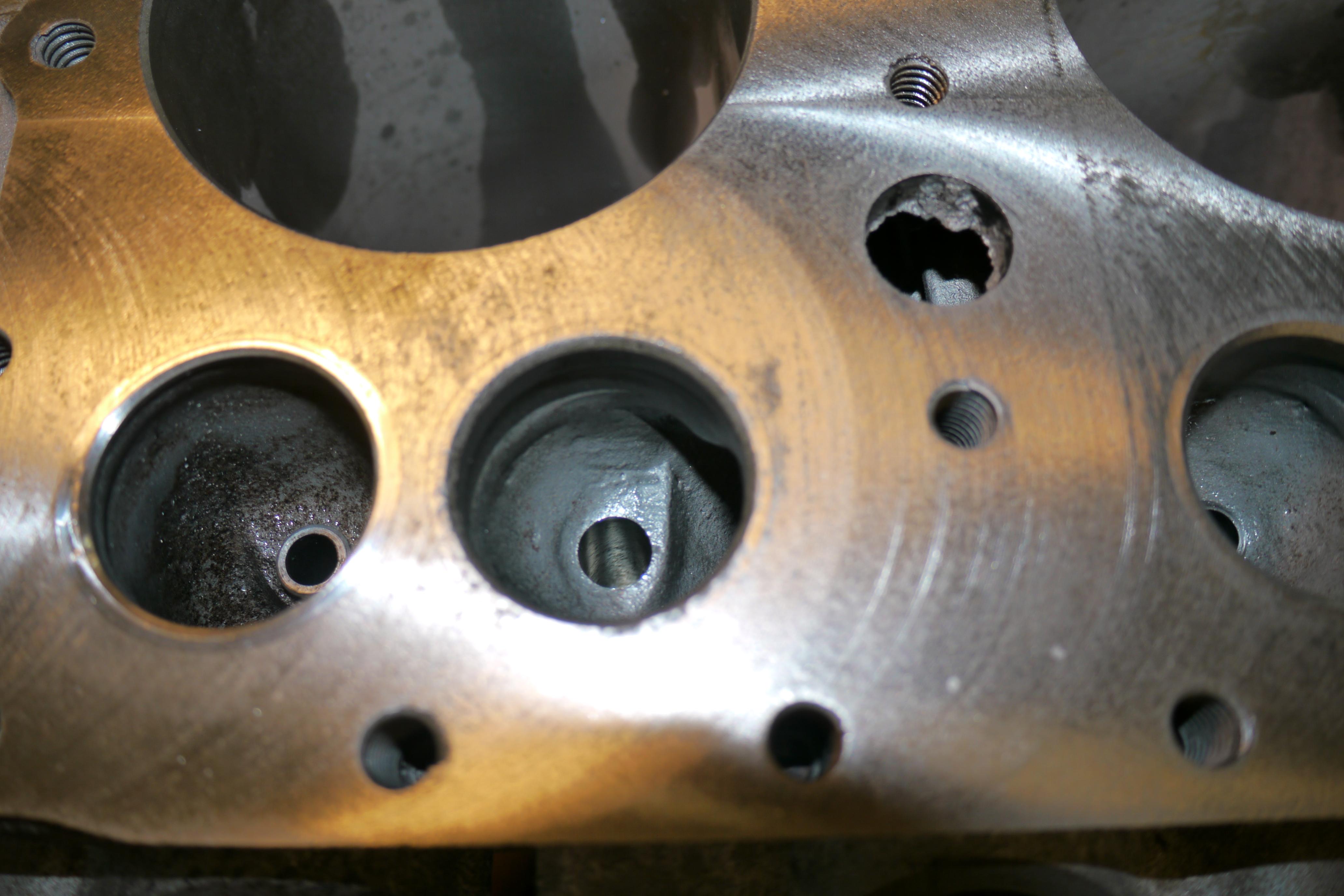
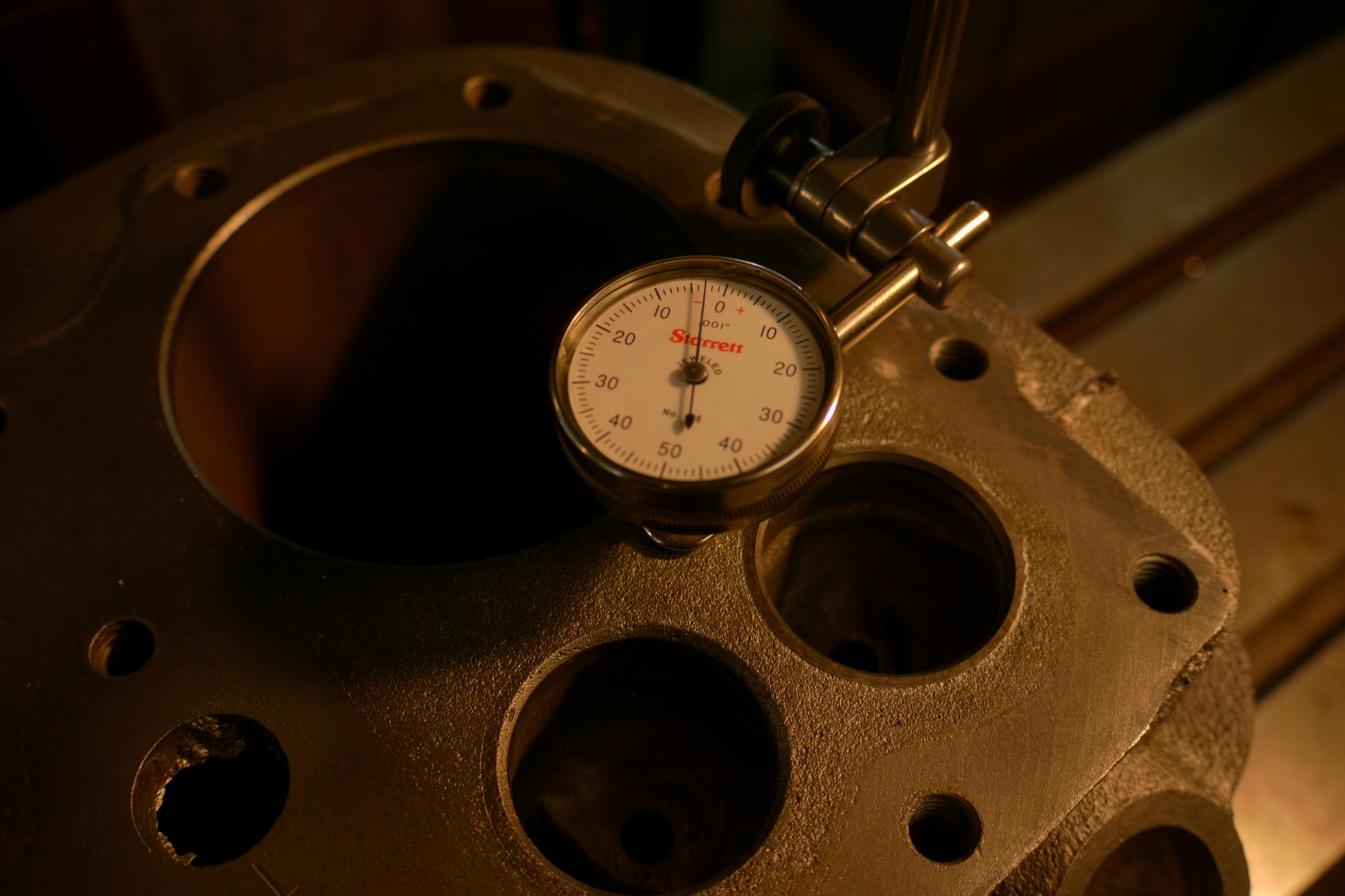
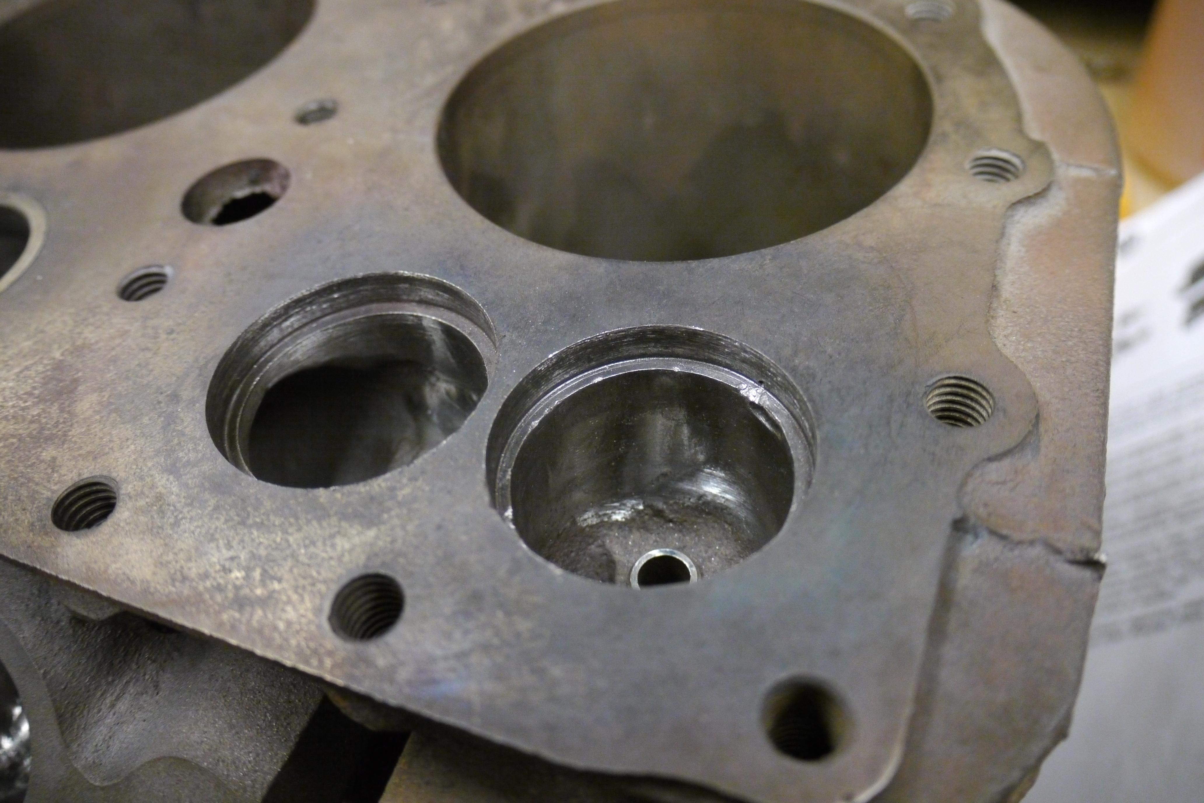
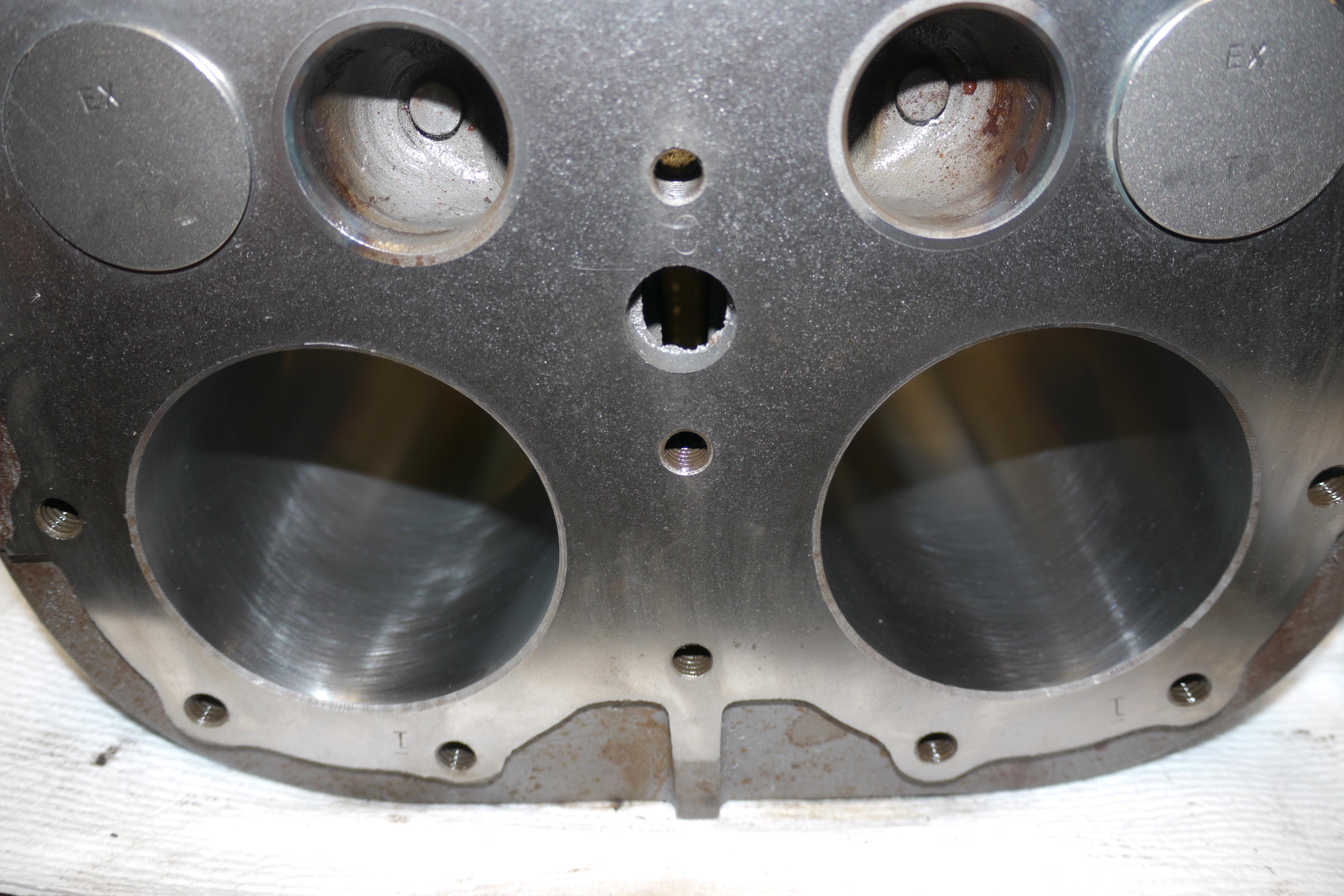
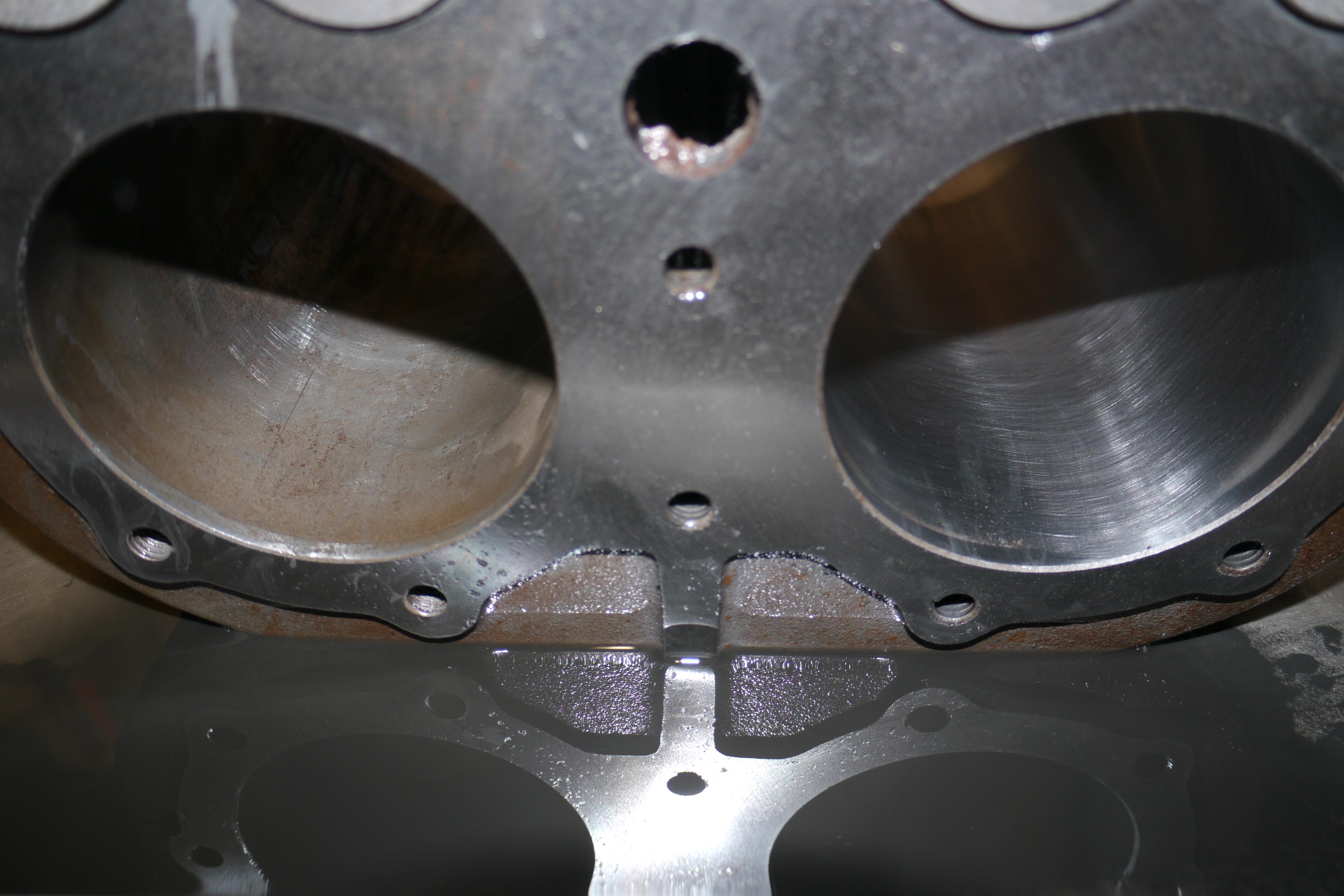
Before I talk about replacing the valve seats I wanted to discuss the fly-cutting of the cylinder jug that took place during the valve guide replacement procedure. As you can see in the pictures there was quite a bit of pitting on the top deck of the cylinder jug. In order to resurface the cylinder jug, the top deck of the cylinder jug must be indicated. I used a spring loaded dial indicator with a good amount of pre-load. I found between 0.005-0.006” of fluctuation along the major and minor axis of the cylinder jug.
I wanted to take this opportunity now that the machine was trammed to fly-cut the deck of the cylinder jug. I had never fly-cut any surface before and had quite a bit of trouble shaping the carbide cutter so that it would cut nicely. As you can see the largest flycutter I can use on the milling machine is just 3-1/2” in diameter. Between passes it leaves a visual ridge which can ever so slightly be picked up by your finger nail rubbing over the surface. Throughout the different stages of the valve guide replacement I tried new chamfered edges on the carbide flycutter, all ending with the same result. By the time I finished installing the new valve guides I had removed 0.007” from the top of the cylinder jug. I was able to successfully clean up and remove all of the pitting from the top deck of the cylinder head, but I was still unhappy with the visible surface finish.
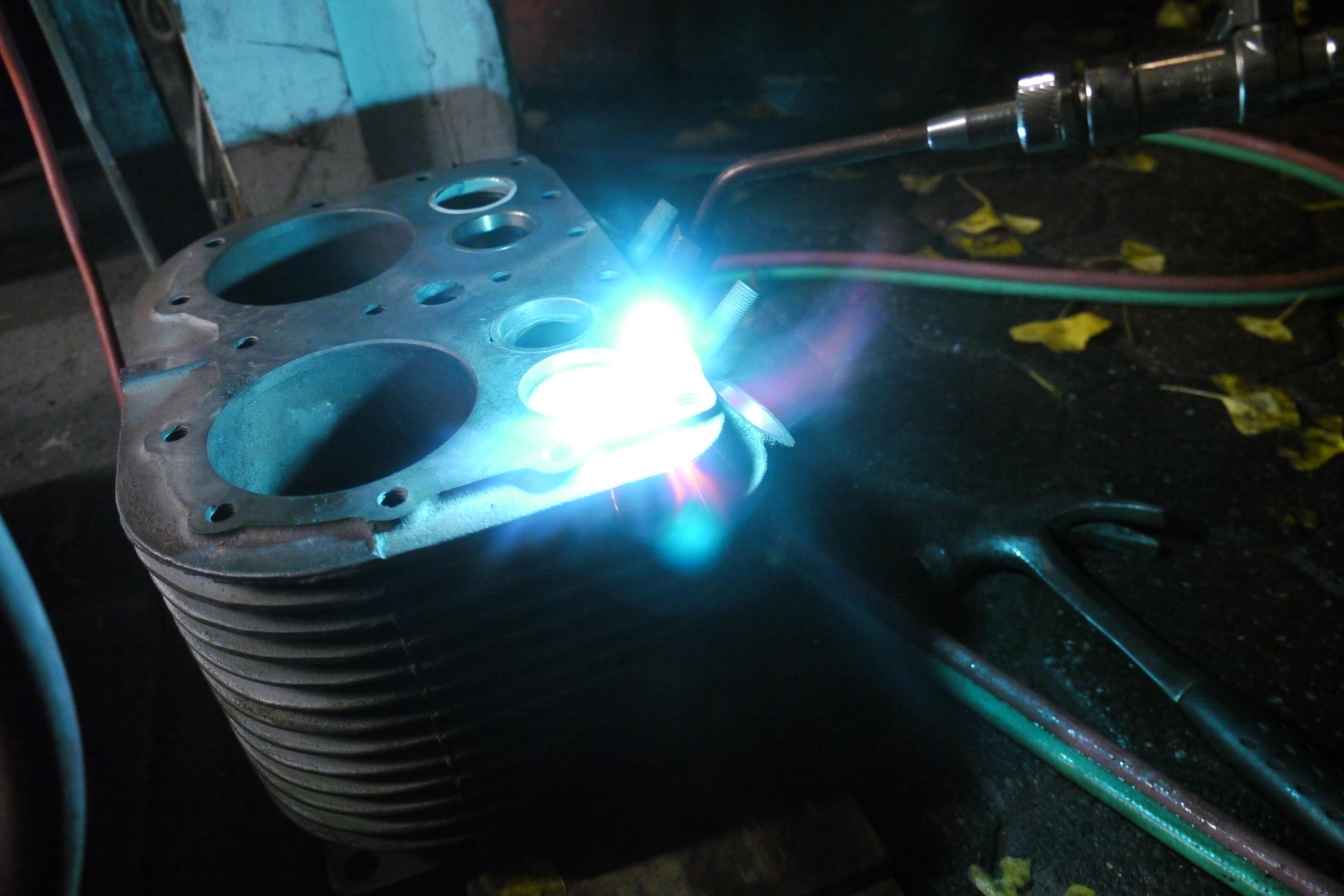
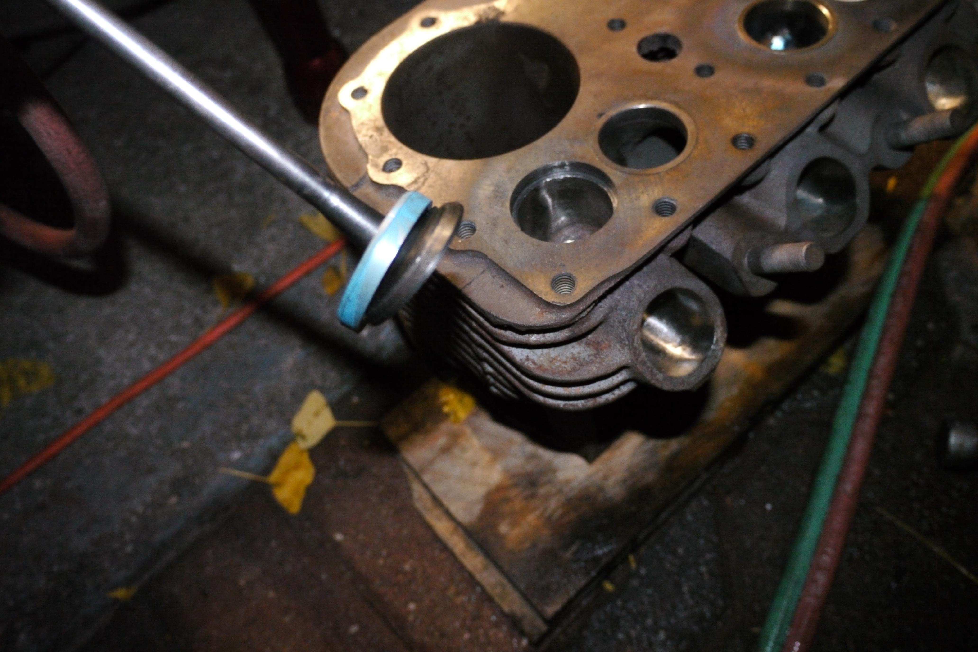
At this time I decided that it was time to pull the intake and exhaust valve seats from both the engine and compressor side cylinder jugs. There are a number of different methods that can be used to pull valve seats. Unfortunately the best methods require some special tools that I do not have yet. I used a vintage Snap-On grease seal puller on a slide hammer to grab the bottom shoulder of the valve seat. The valve seats were very stubborn and required the use of an oxy-acetylene torch to super-heat the block around the valve seats to facilitate removal. I was able to remove all six of the valve seats with success.
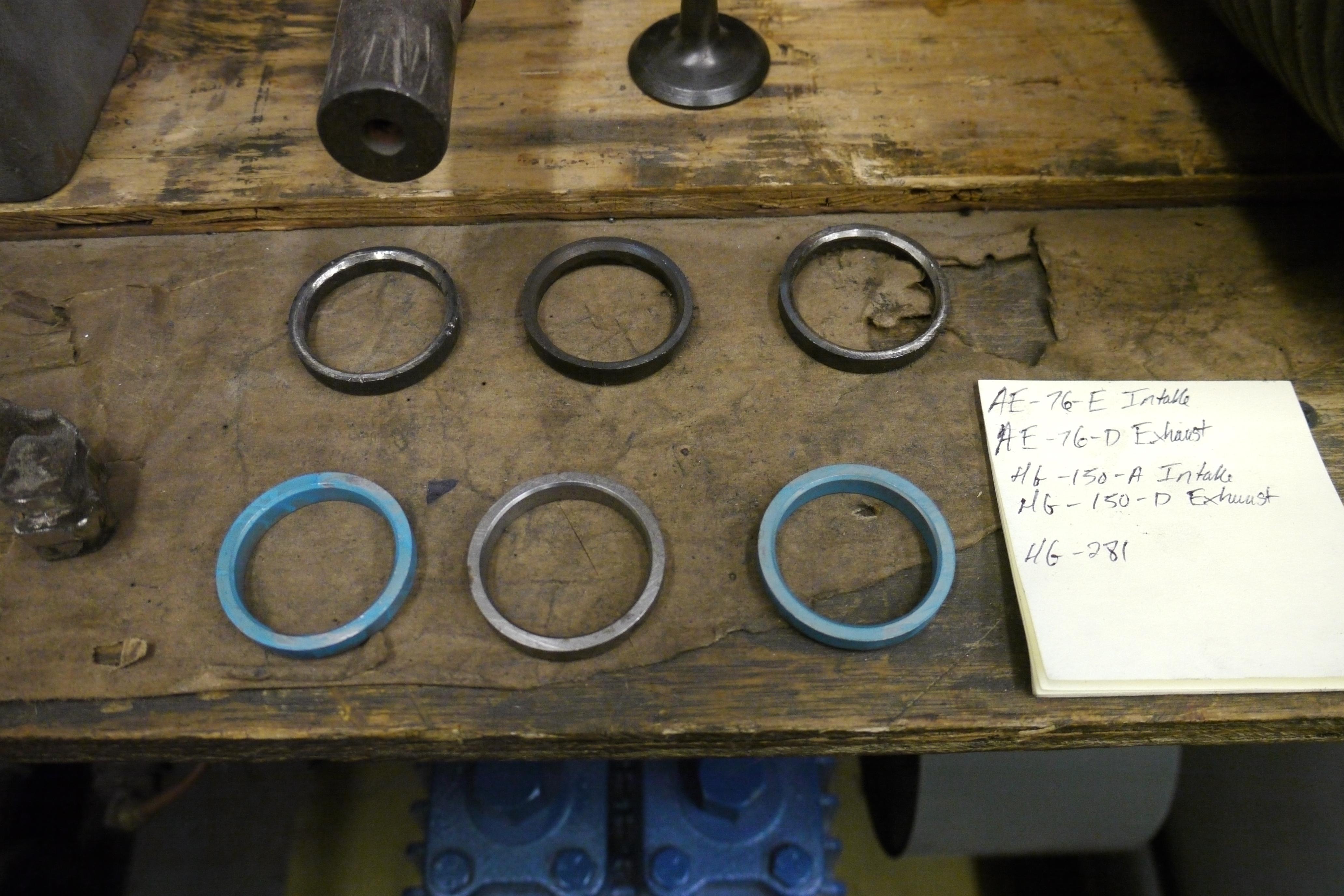
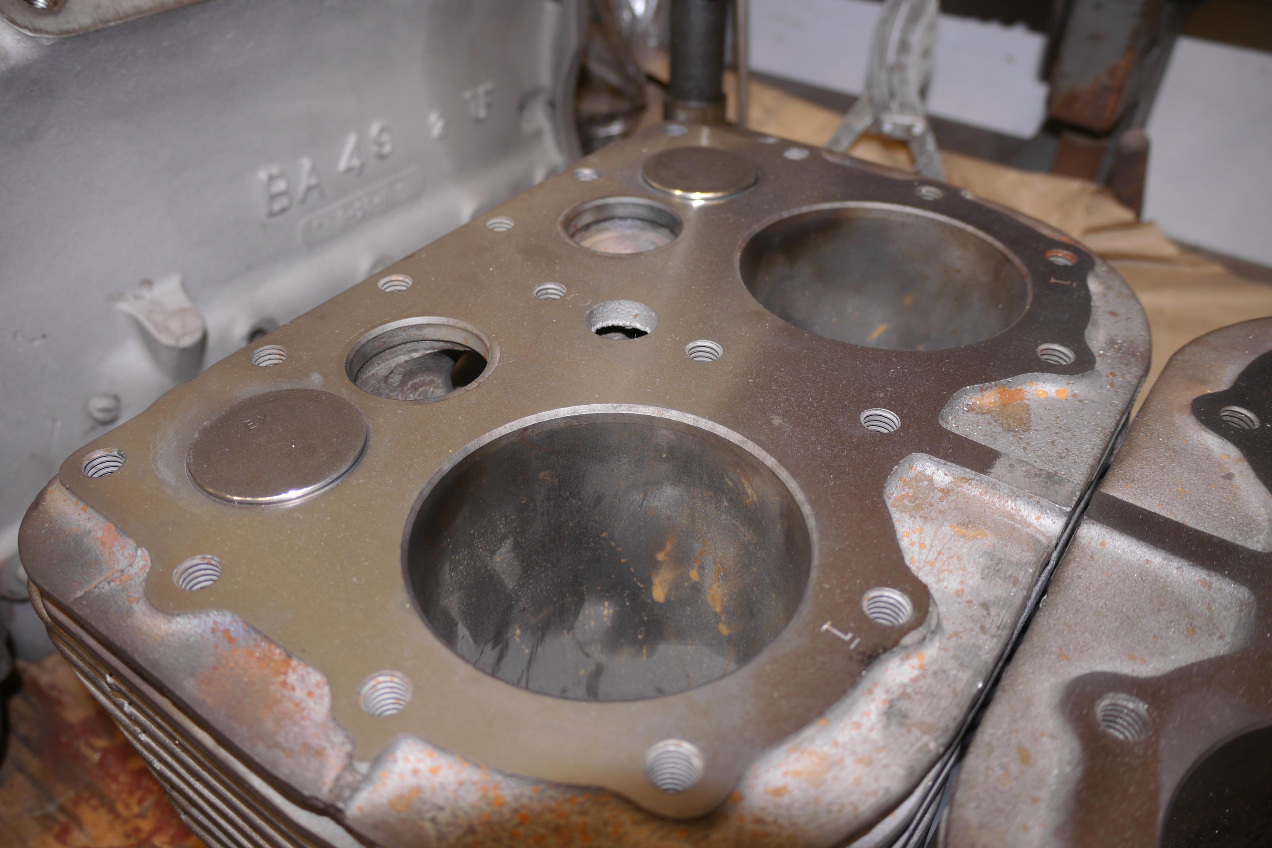
One of the valve seats was exceptionally stubborn and pulled out a small chunk of the cylinder jug casting out with it. This is for the most part my fault because I was not using the proper tool for the job. The best method for removing valve seats is with an expandable collet head for a slide hammer. I hope to have this tool before I rebuild the other Schramm engine that I have. After removing all of the valve seats, I spent a little time cleaning up the valve seat reliefs so that new valve seats could be installed. In the years after this compressor was made, Wisconsin began using stellite hardened valve seats. Because I am using the harder stellite exhaust valves in this engine, it was only logical to replace the exhaust valve seats with stellite seats. Installation of the new valve seats is very straightforward. Once the shoulder on the valve seat relief is clean, you simply heat the immediate area with an acetylene torch. With a new valve seat on hand, you can drive the new valve seat into the cylinder jug with an old valve and an ordinary hammer. You can audibly hear when the new valve seat is driven completely down. It does not take much to drive the new seat into the cylinder jug. Two of three light taps is all that is necessary. From the factory there is a 0.002” interference fit between the valve seats and the cylinder jug.
The same procedure was performed to the compressor side cylinder jug.
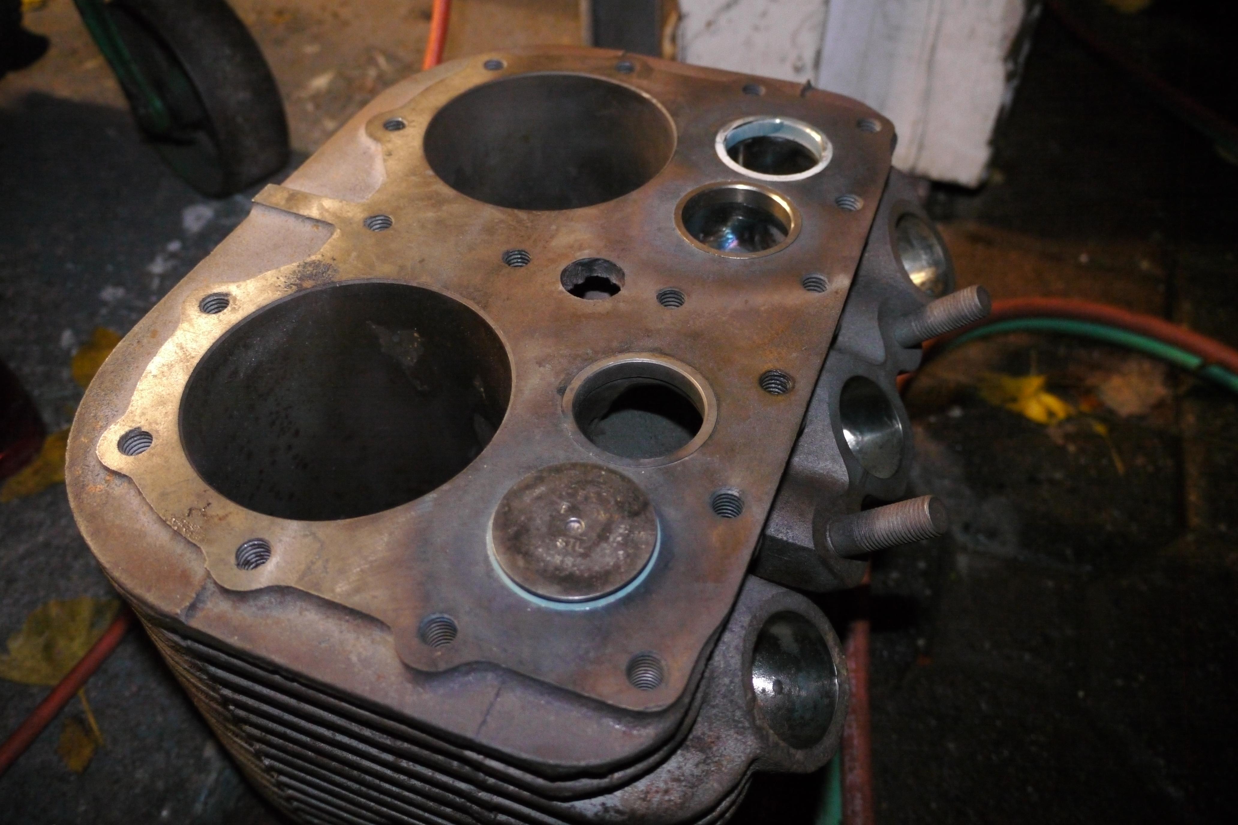
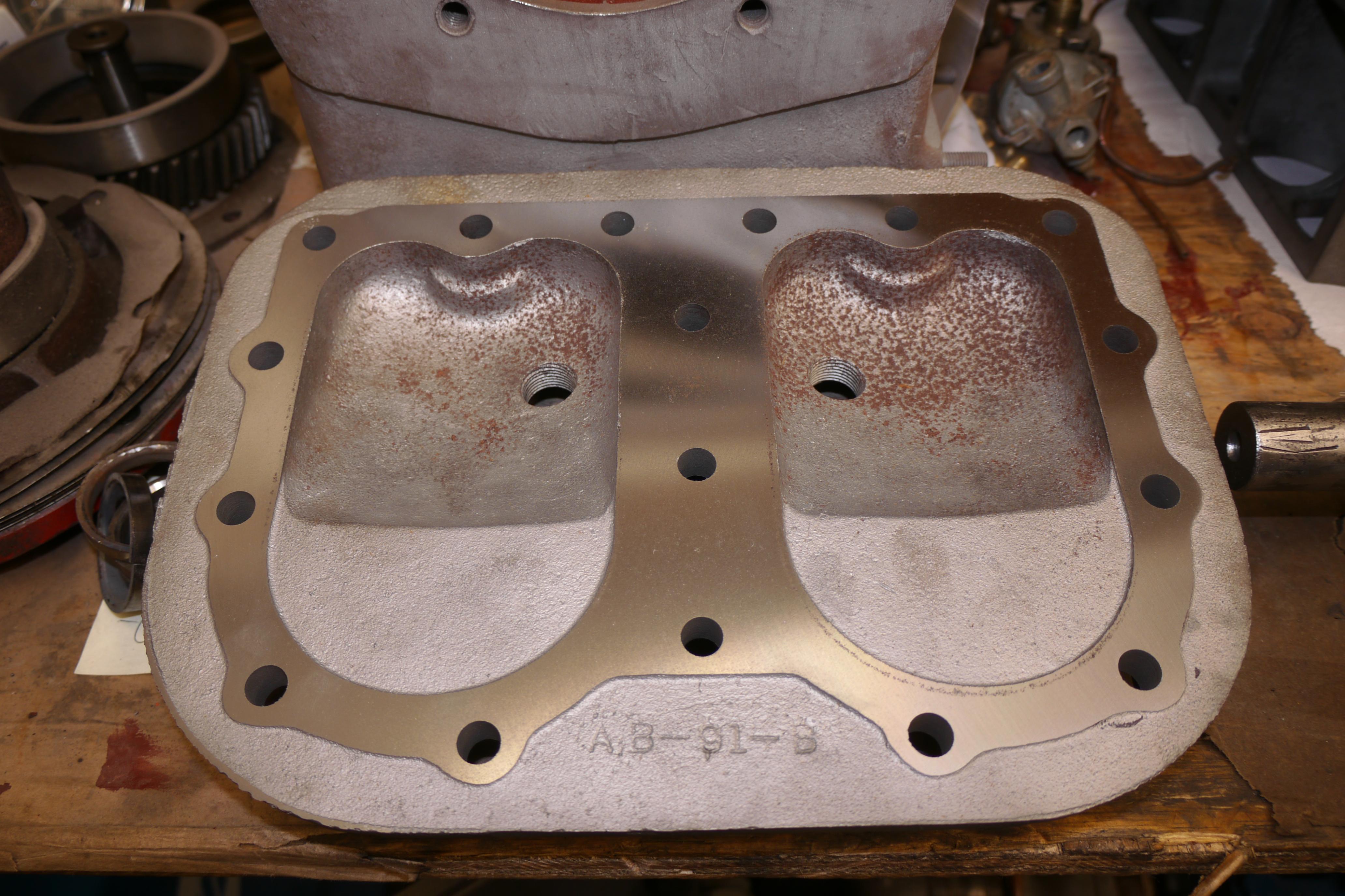
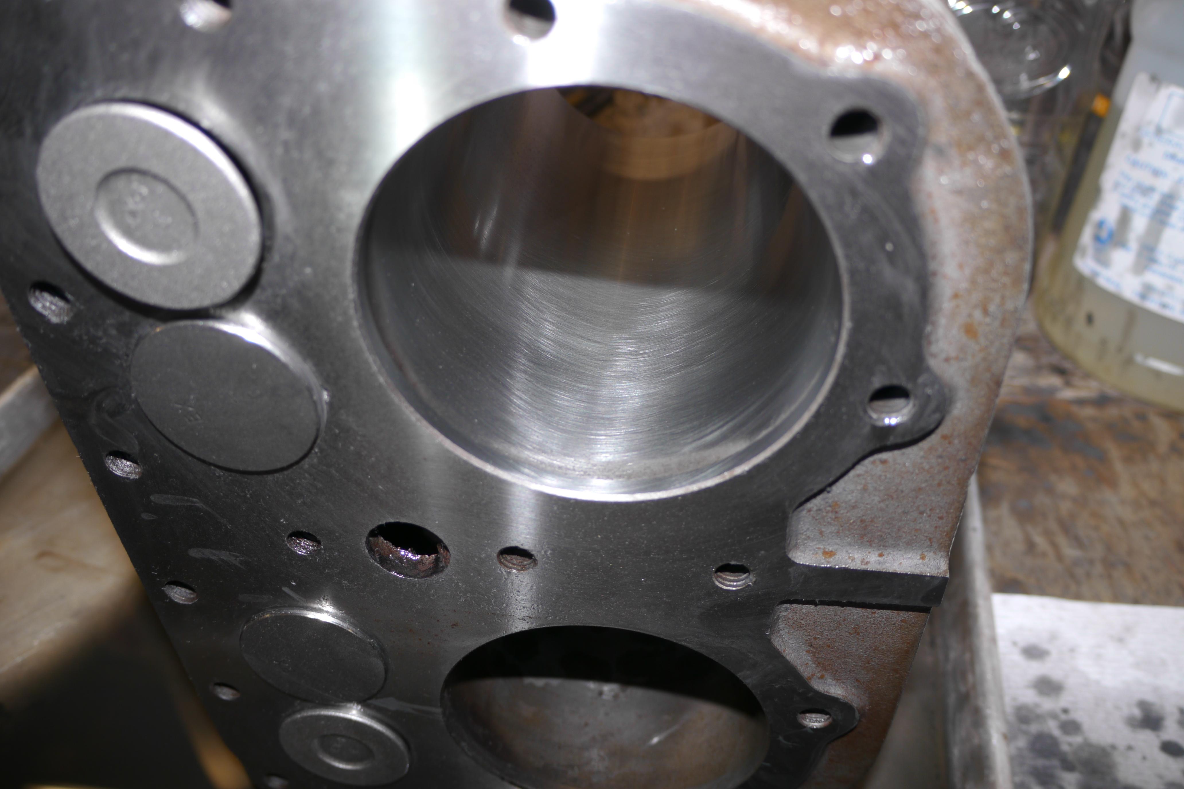
The valve seat removal process is much more difficult than the replacement procedure. With all new valve seats and guides in the cylinder jugs, it was time to have the cylinder jugs and cylinder heads professionally resurfaced so that I could hone the cylinders and cut the new valve seats at home. I just could not get a satisfactory surface on the decks of the cylinder head with such a small flycutter. I ventured over to a friends shop in south central Pennsylvania to use his bigger equipment. After indicating the cylinder jug on the Rottler mill, a 0.002” pass was all that was necessary to clean up the surface finish of the cylinder I attempted to fly cut at home. At this stage I had removed 0.009” of material from the cylinder jug on the engine side of the compressor. Only 0.003” of material had to be removed from the compressor side cylinder jug. Likewise only about 0.003" of material was removed from the cast iron cylinder head. The aluminum Schramm specific cylinder head was not touched.
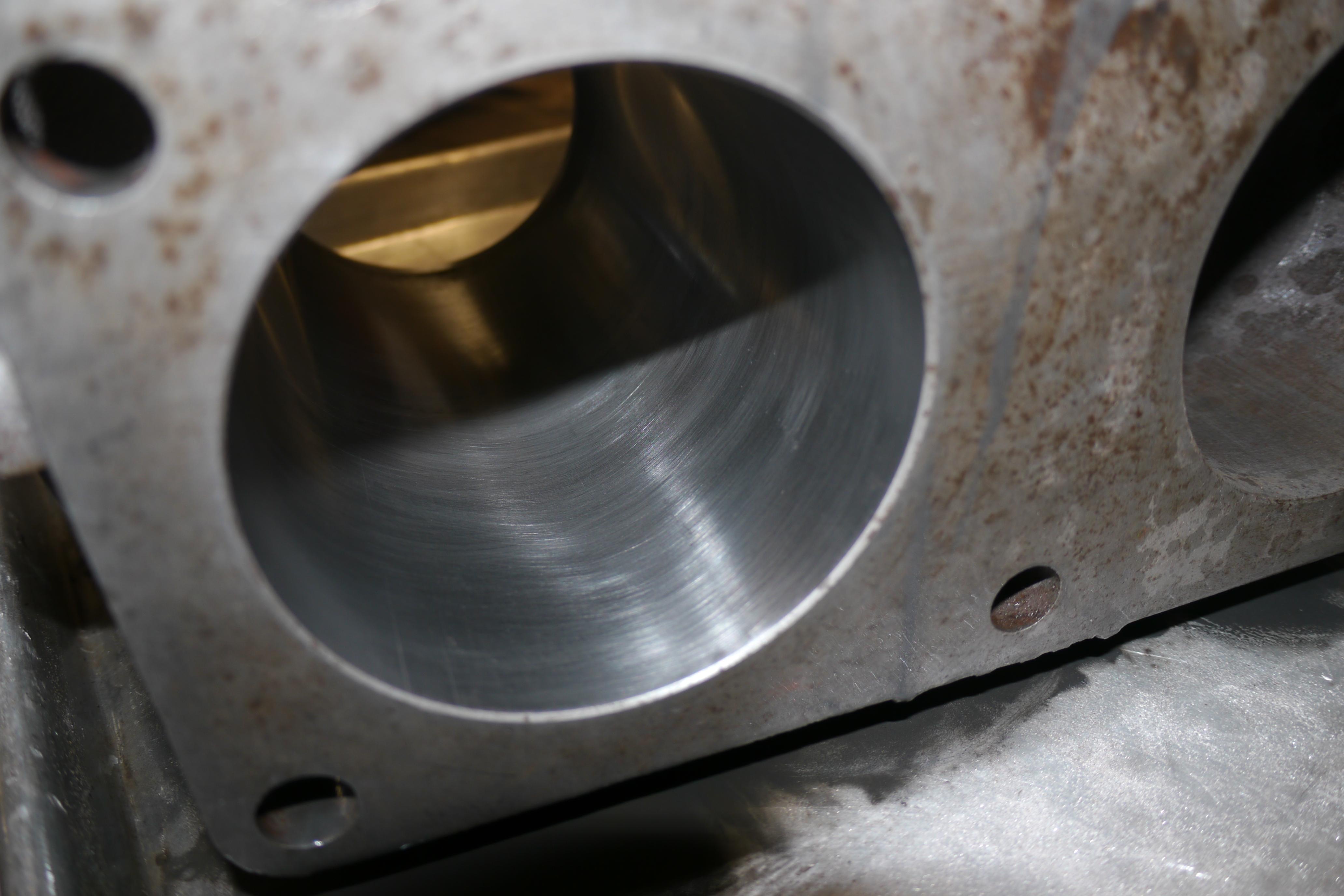
With all of the major machine work finished, I was able to focus on the last step of the machining process, honing the cylinders.
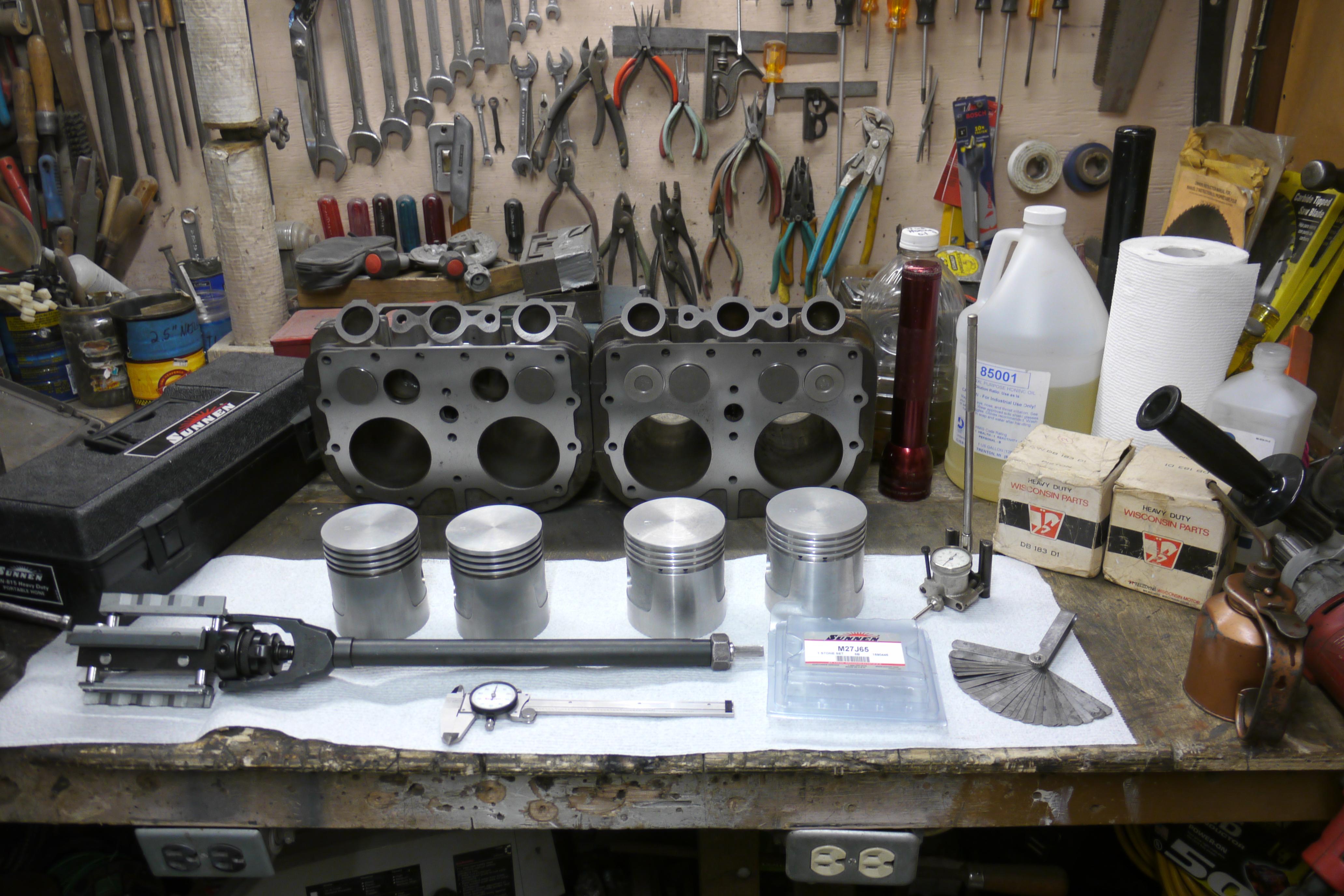
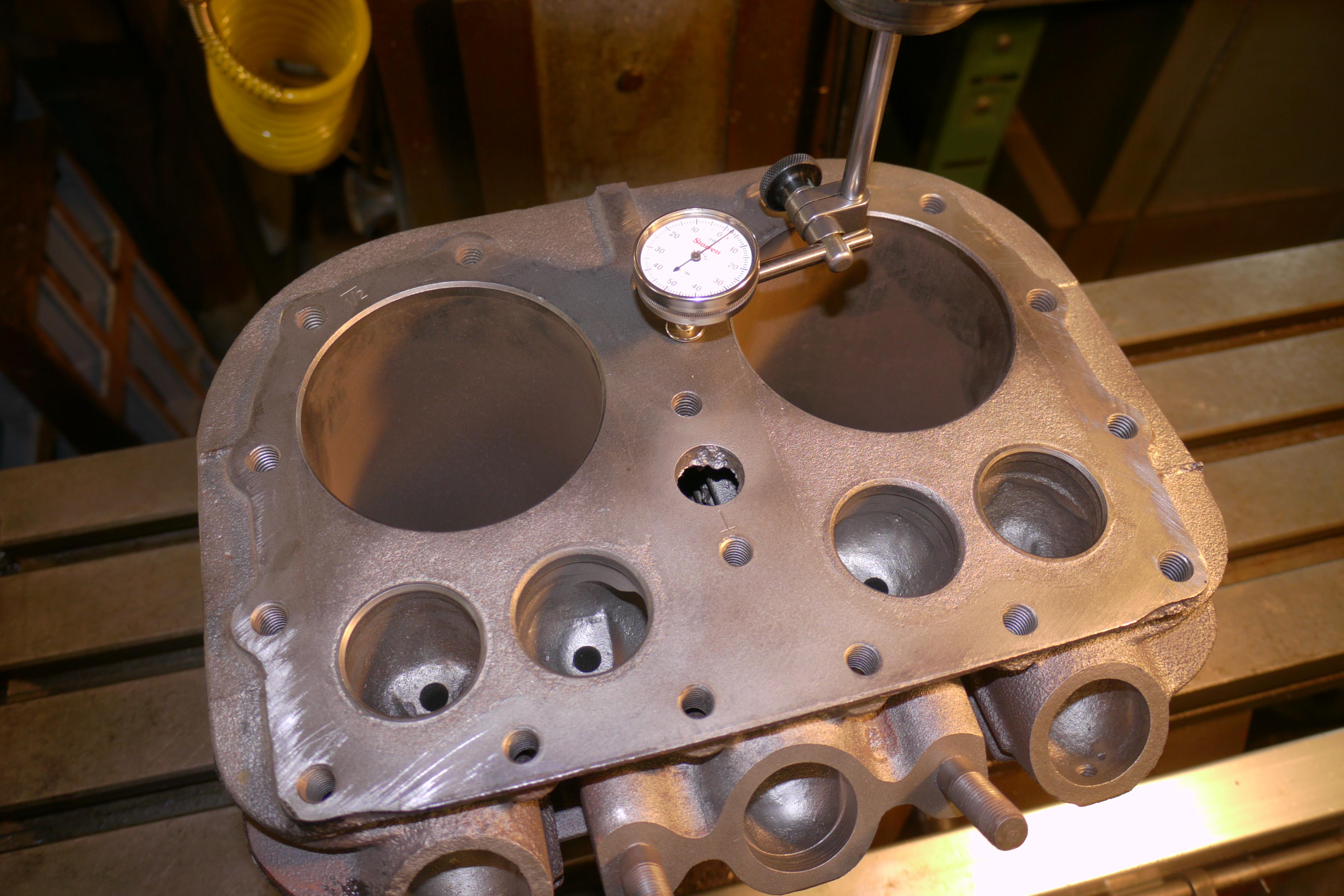
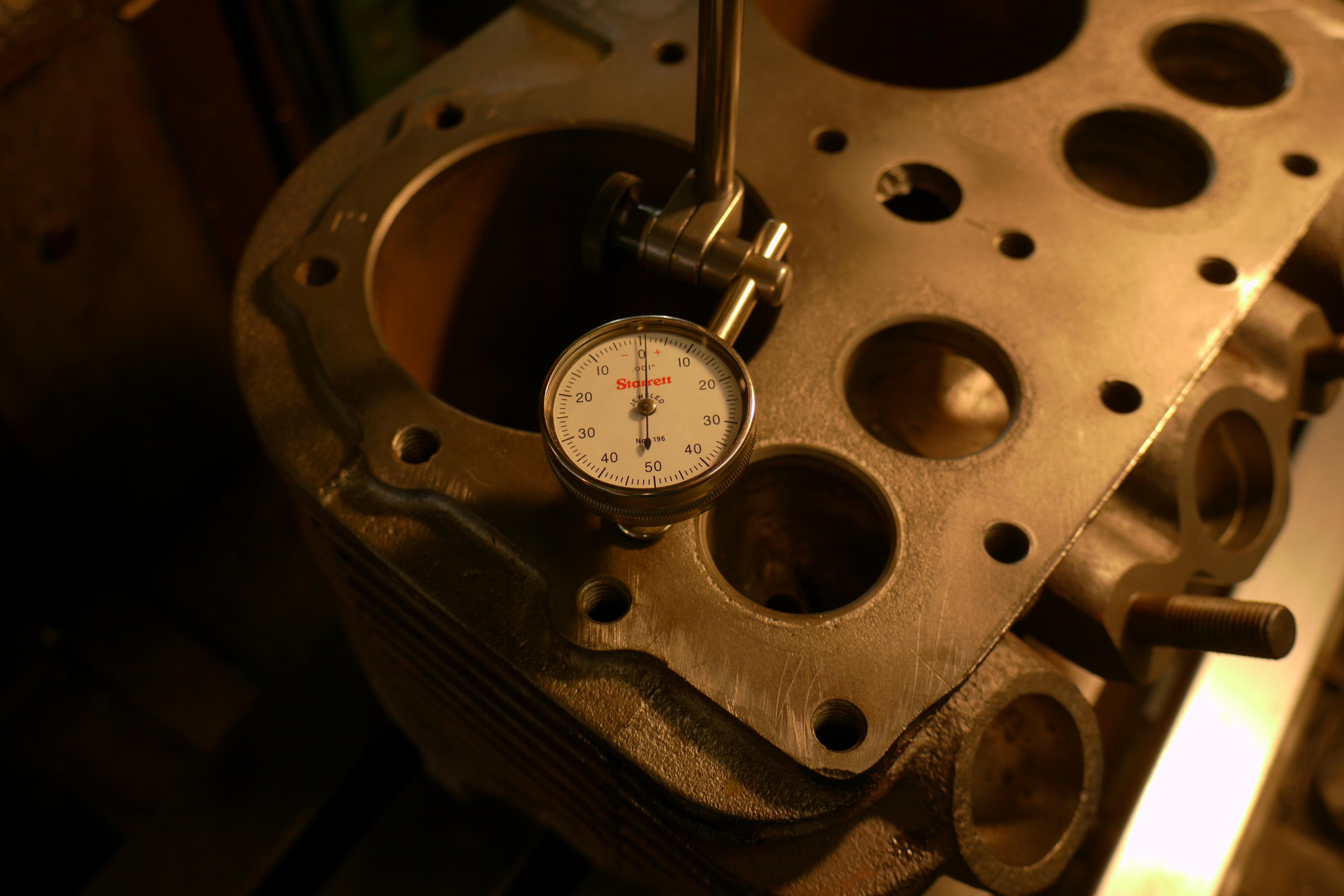
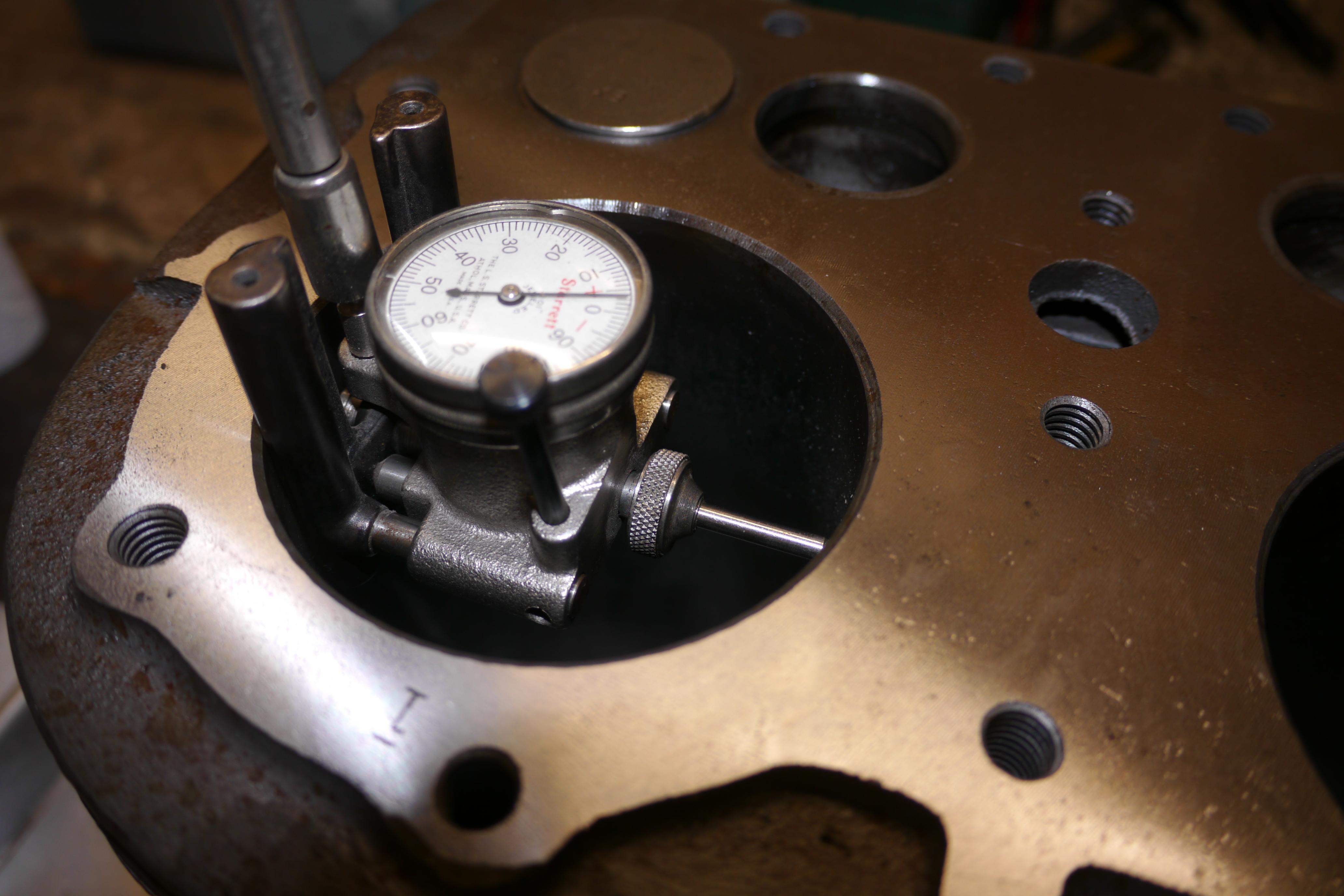
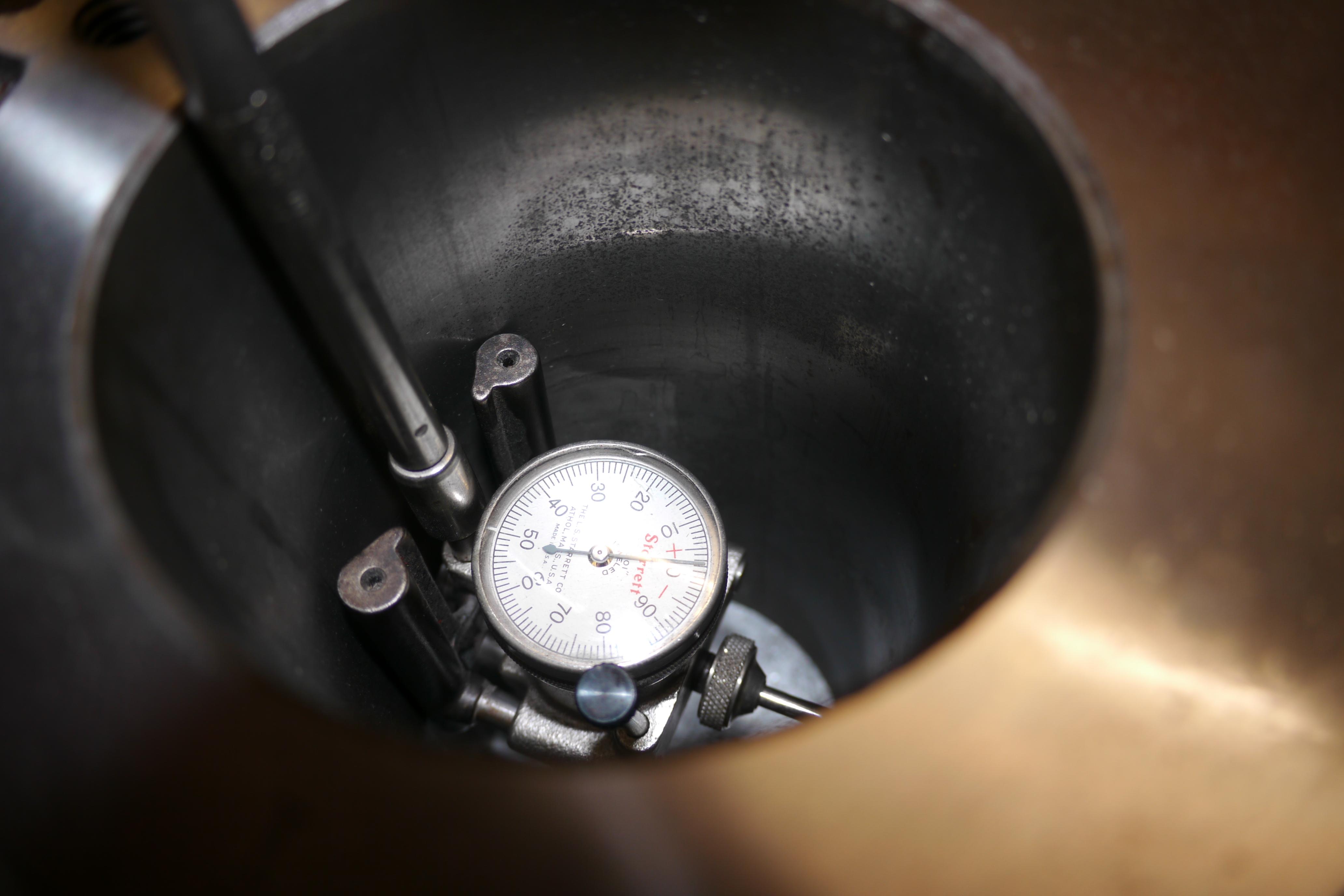
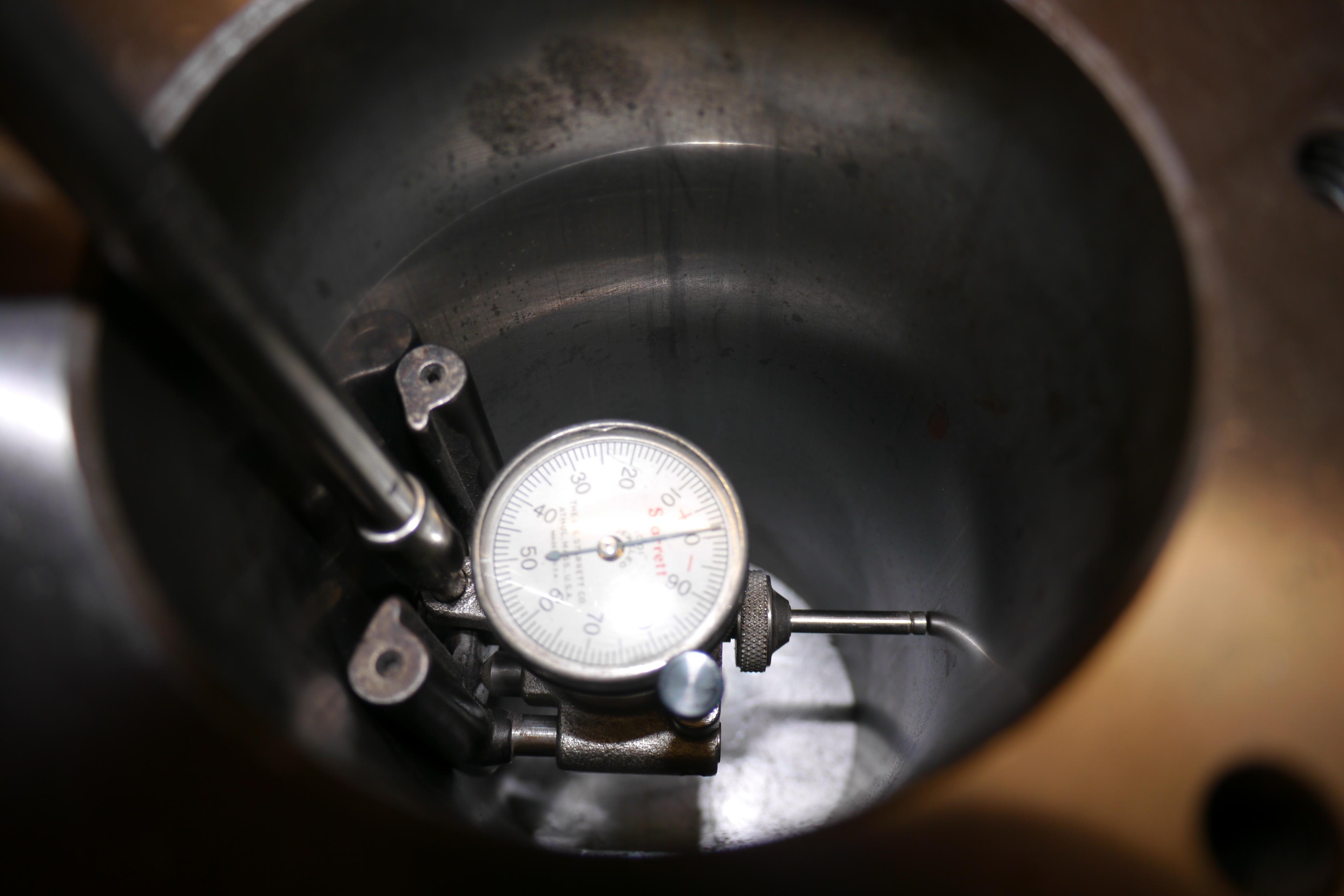
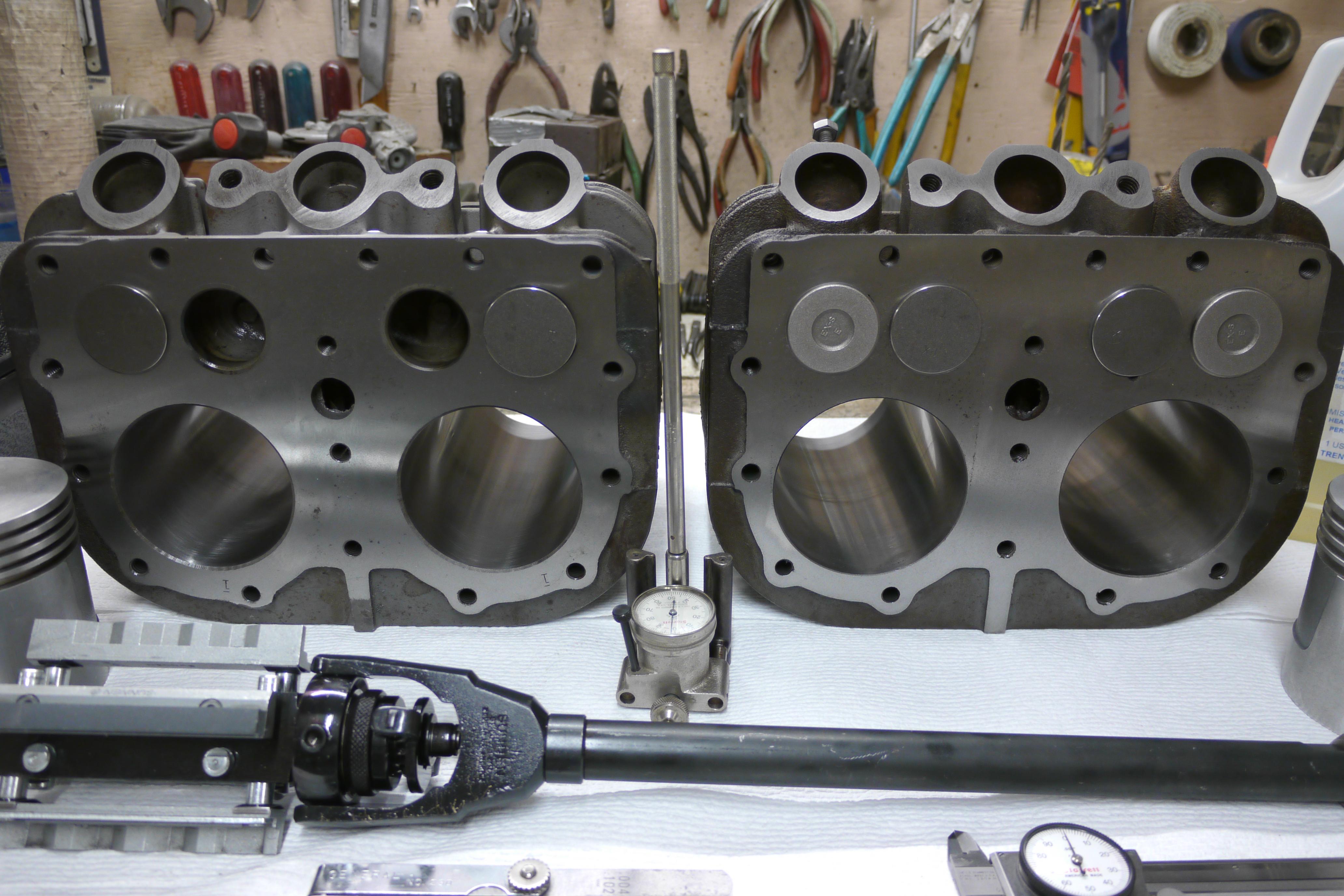
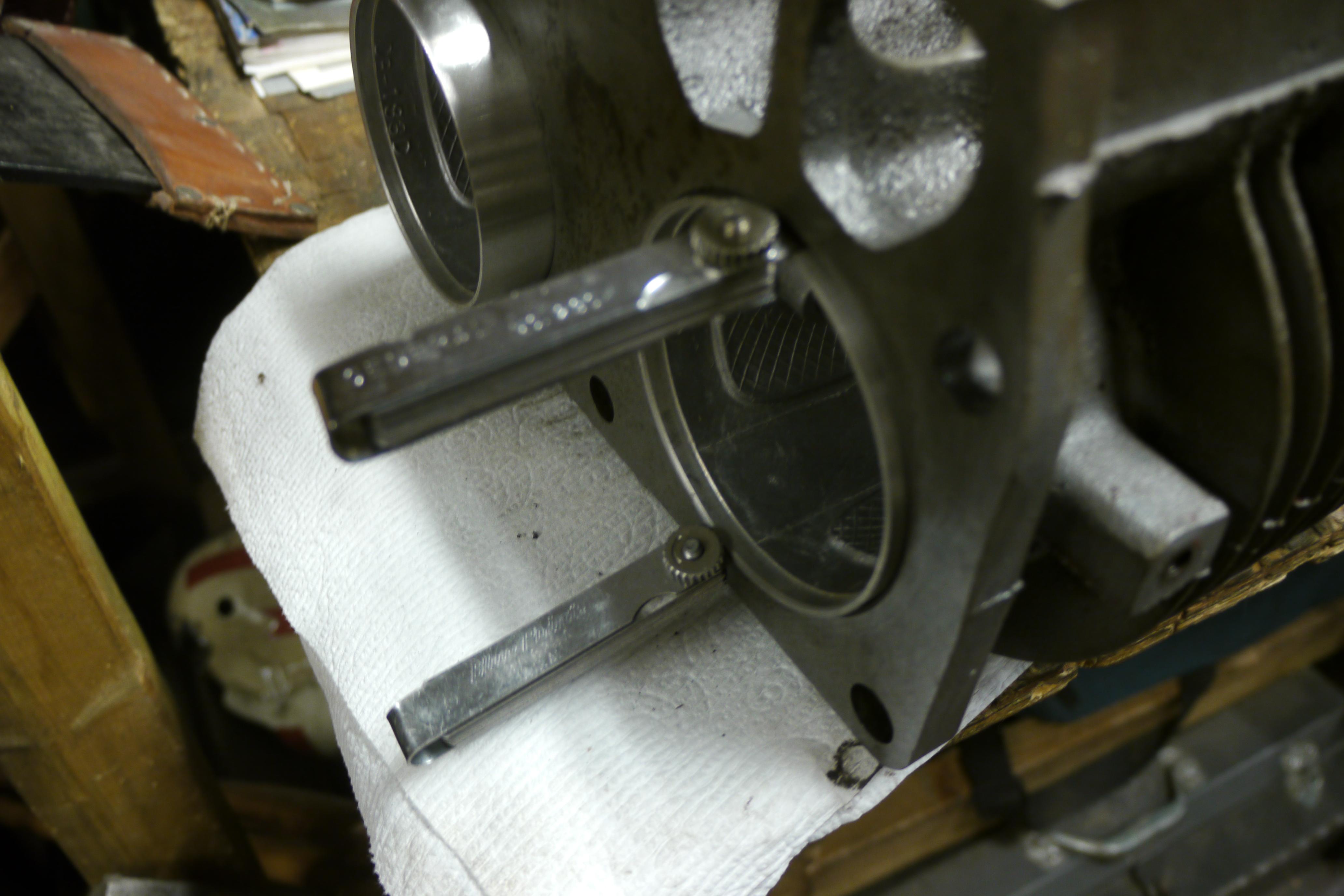
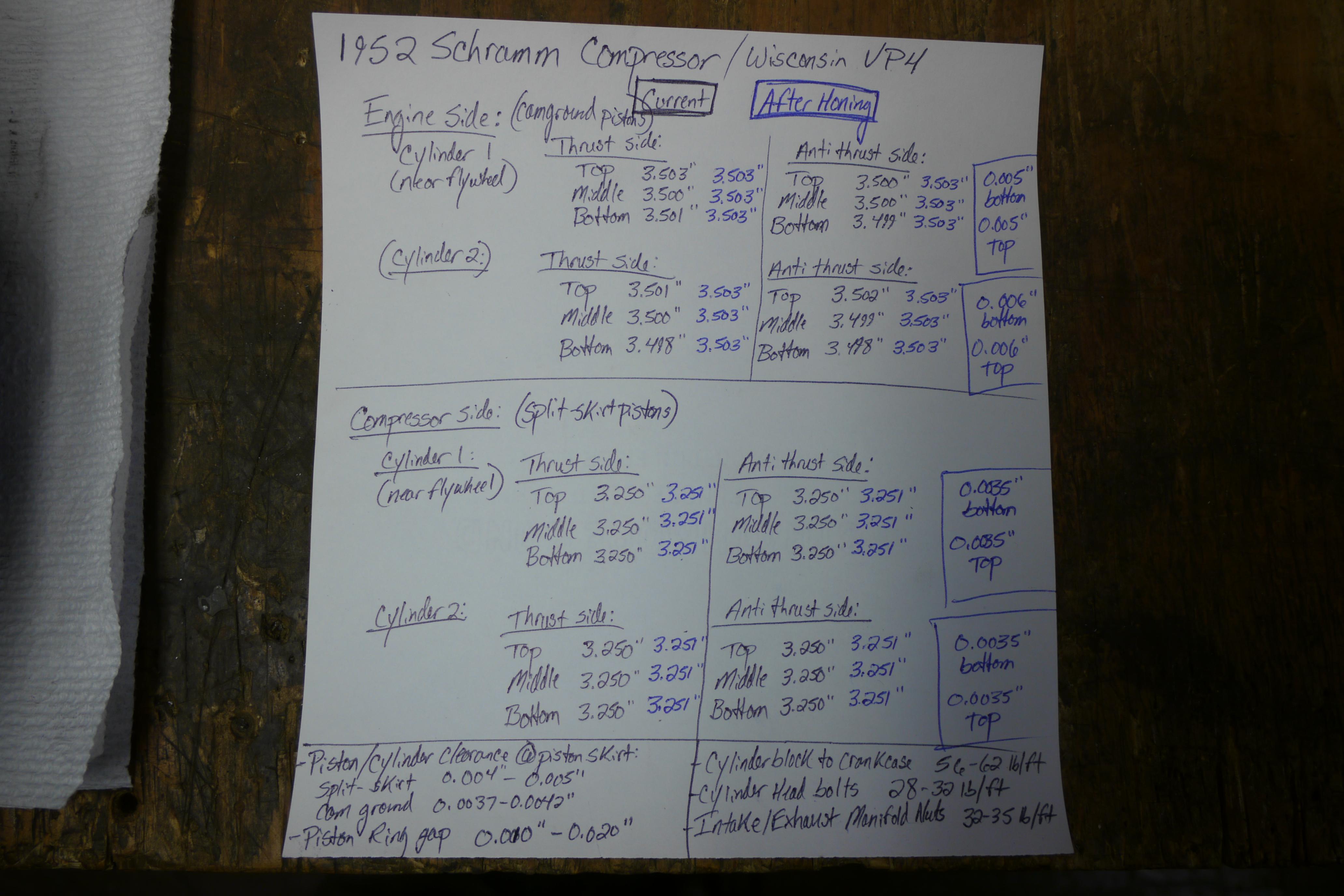
Before honing the cylinders I used my Starett bore gauge to measure the size and concentricity of each cylinder. It is important to take measurements of the thrust and anti-thrust sides of each cylinder at the top, middle and bottom to get an accurate read on cylinder size. On the engine side of the compressor, I had 0.002” of taper on the front cylinder and 0.003” of taper on the rear cylinder. On an air cooled engine, the cylinder furthest from the cooling fan usually runs hotter and leaner, resulting in accelerated wear. On the compressor side cylinder jug, I found that both cylinders were true all around showing very little wear. There was virtually no taper from the top and bottom of either of the cylinders. I concluded that both cylinder jugs should clean up at standard bore, but the only way to know would be to hone the cylinders and see what the piston to cylinder clearance is once a nice cross-hatching can be established in all cylinders.
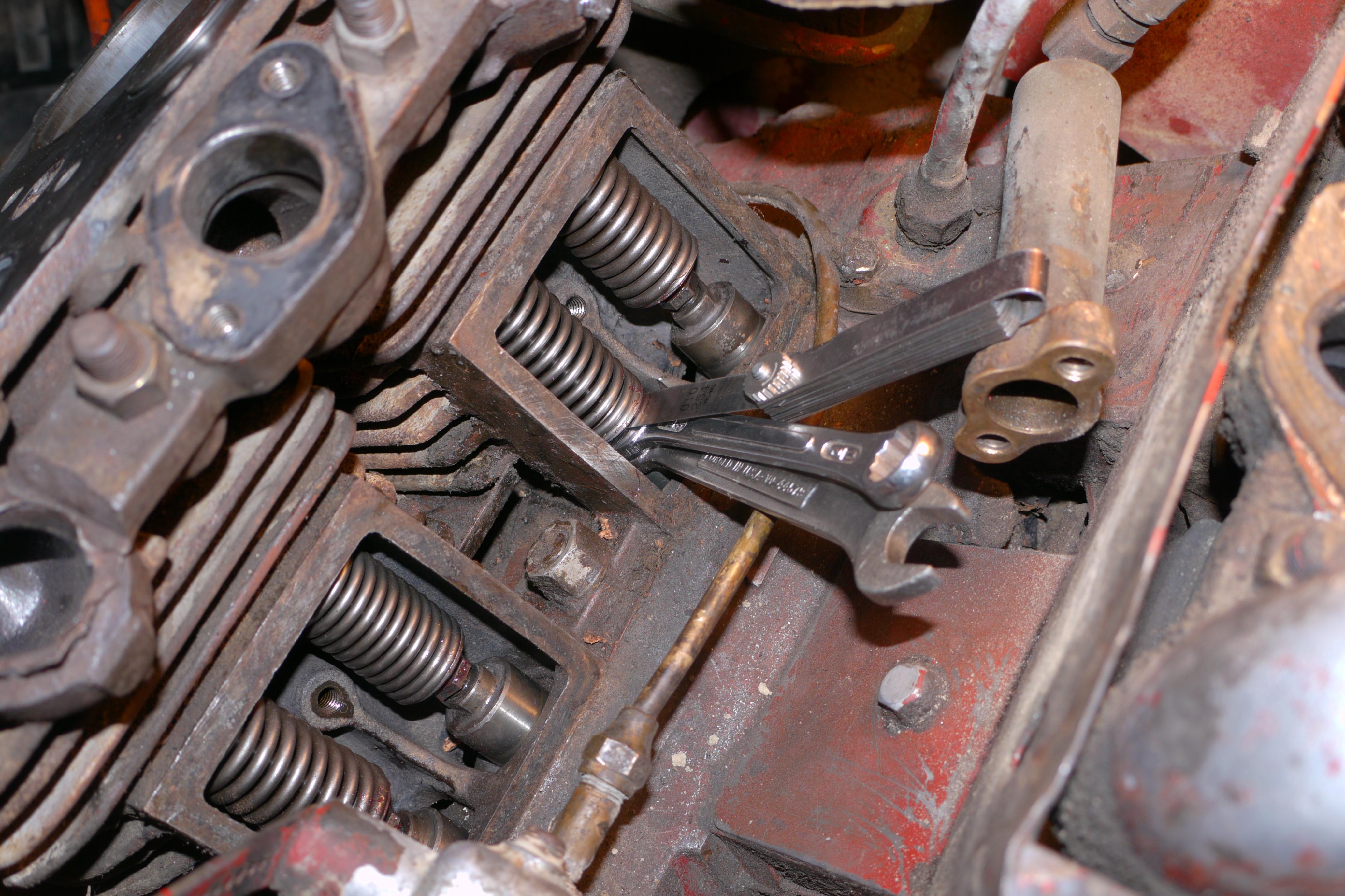
Because I updated the engine side of the compressor to cam ground pistons, I had to obey the new 0.0037”-0.0042” piston to cylinder clearances mandated by the service manual. These measurements are the total piston to cylinder clearances, not the clearance on both sides of the piston! This means that a 0.004" feeler gauge should slide between the skirt of the piston and the cylinder, and a 0.005" feeler gauge should not. Unfortunately I was misinformed about this information and accidentally bored the cylinders oversize thinking that a standard piston and rings would be fine with 0.004" clearance on both sides of the piston. I caught this error before assembly, and ended up re-checking piston to cylinder clearance and discovered that I would need 0.010" oversize pistons for the engine side of the compressor, and 0.010" oversize pistons for the compressor side. Finding oversize pistons and rings for the engine side of the compressor was no problem at all, but finding pistons for the compressor side was a nightmare. Since the compressor side of the engine is based out of a Wisconsin VM4, an engine which was obsolete in 1950, it has proved exceptionally difficult to find oversize replacement pistons for it. It took me four years to find a matching set of oversize pistons for this compressor. Sadly they are 0.020" oversize and not the 0.010" oversize pistons I had wanted.
After intitial honing of the engine side of the compressor I thought I had 0.005” and 0.006” of piston to cylinder clearance; 0.0008” and 0.0018” respectively over the maximum clearances allowed by Wisconsin. However the piston to cylinder clearance was actually 0.010" and 0.012"; 0.0058" and 0.0068" respectively over the maximum allowable clearance. In order to correct this mistake I had to source oversize pistons for the engine and compressor sides of the compressor. With the appropriate measurements now in mind, I bored the engine oversize and finish honed the cylinders until I had 0.004" of piston to cylinder clearance for the cam ground pistons on the engine side of the compressor, and 0.0035" piston to cylinder clearance on the compressor side of the engine.
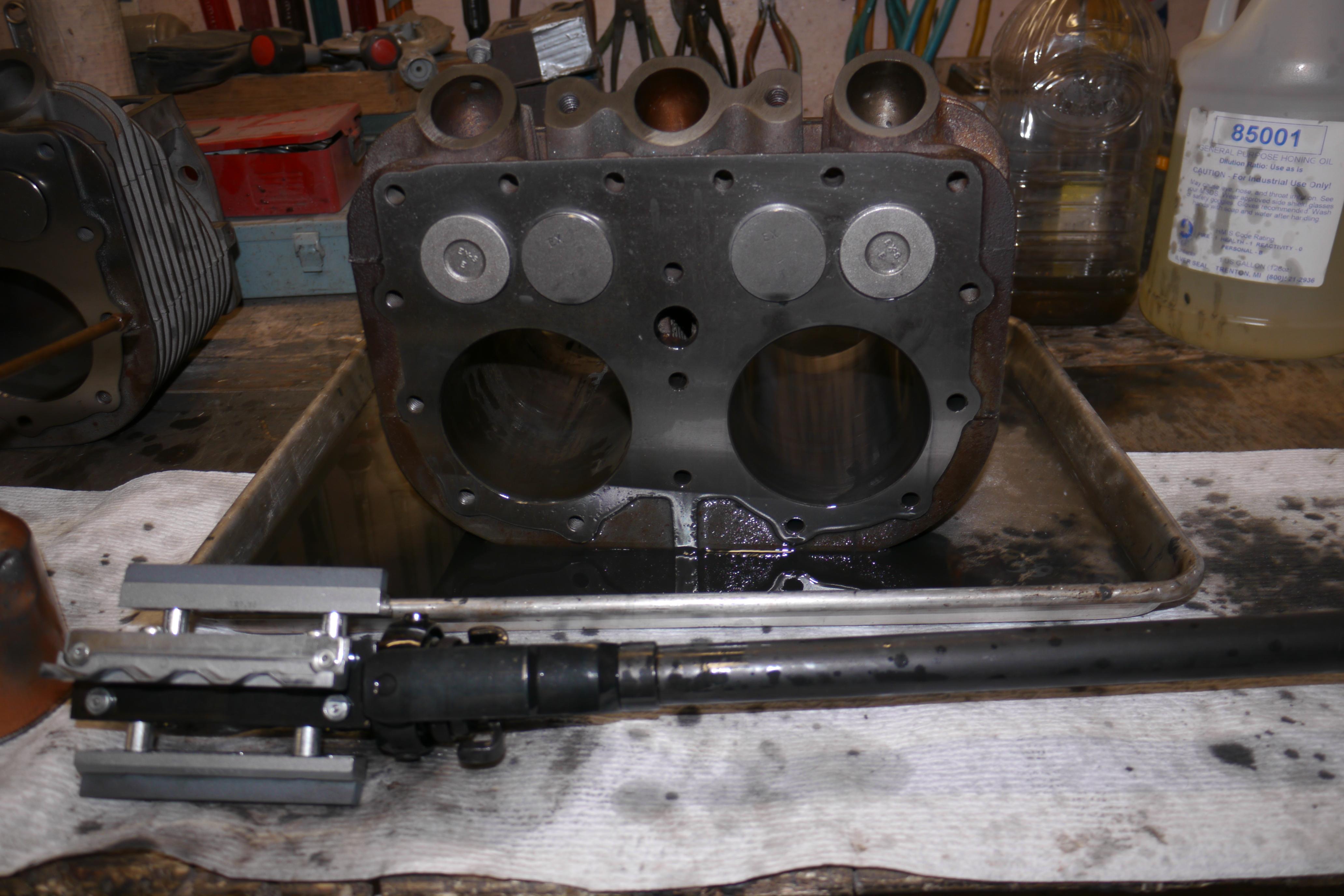
In regards to the honing procedure itself, some special tools are necessary. Some folks use wood dowels with sand paper to hone cylinders, a lot of people use cheap spring loaded hones you can find at your local auto parts store, a select few use ball hones, but the professionals use rigid body hones. Because I collect and restore a lot of antique engines I had decided long ago that I was going to buy a Sunnen rigid body portable hone. A couple years ago I was very lucky to pick up a brand new Sunnen AN-815 heavy duty portable hone for half of what they typically cost new. Knowing that Wisconsin cylinders are cast iron, I was able to order away for the correct honing stones. In this case I used the Sunnen AN-500 280 grit honing stones. I do not have a Sunnen honing machine, so I spent some time setting up my temporary honing station. It consist of an aluminum baking sheet, a gallon of honing oil, an oil can, paper towels, a set of feeler gauges, a cylinder bore gauge, a rheostat, an electric drill and of course the hone. Before the honing process can begin, it is important to calculate the optimal honing rpm. Optimal honing rpm is calculated by dividing 1200 by the bore diameter in inches. In this case 1200 / 3.5” = ~345 rpm. Because my ½ inch electric drill does not have such fine rpm adjustment, I hooked up a shaft driven tachometer to the end of my drill. With a heavy duty rheostat I was able to adjust the voltage down so that the drill would operate at the correct speed. With the drill dialed in, I filled my oil can with honing oil and sprayed oil all over the cylinder that was to be honed. Now is a good time to remove any ridge that might exist on the top of the cylinder with a ridge reamer. In this case no appreciable ridge was measured. My Sunnen AN-815 rigid body hone has micrometer adjustment, allowing me to easily measure how much material is being taken off. I like to start honing just under standard size, so I set up my hone to 3.499” and adjust from there.
The hone has four guides to ensure that the hone is following and correcting any flaws in the cylinder. With plenty of honing oil being squirt around the hone, I was able to remove a small trace of the cylinder finish, locating the high and low spots. When honing it is a good idea to move the hone in and out at a pretty consistent rate to ensure the stones are not working in the same area too long causing irregularities in the stone or valleys in the cylinder. You want to move the hone in and out to create the crosshatching pattern that oil is carried and guided by when the engine is operating. Honing is a slow process and must not be rushed. It takes on average twenty minutes to a half hour to clean up a cylinder of this depth sufficiently.
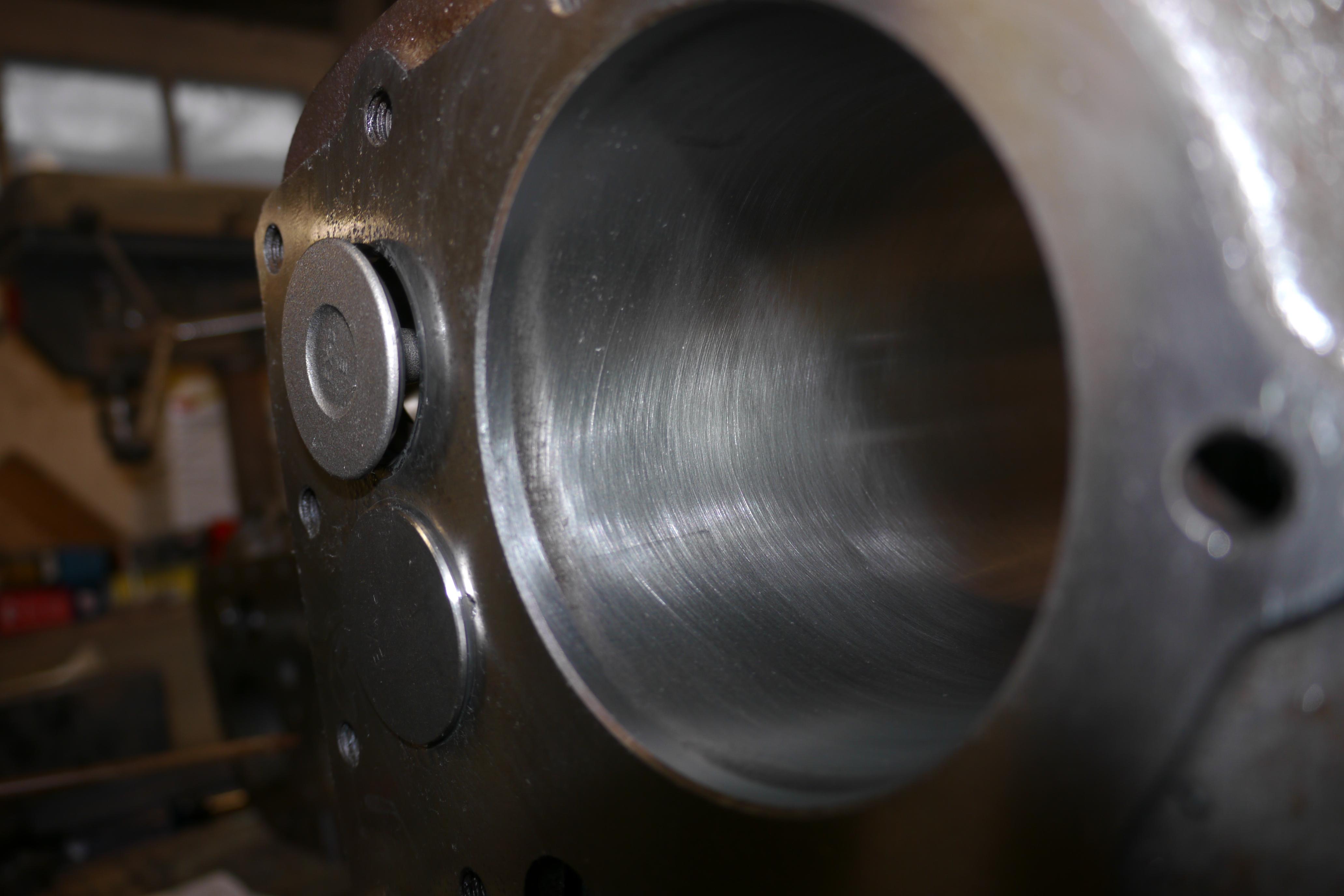
I like to stop and measure the bore of the cylinder every few minutes to see where the bore falls in relation to how much needs to be cleaned up. With the maximum allowable piston to cylinder clearances in mind, I slowly crawled up to that diameter and noted that the cylinder would not clean up sufficiently. I continued honing taking off very little material until I was happy with the surface finish. In a lot of instances, heavy scoring, rust pitting and exaggerated cylinders will need to be bored oversize. Wisconsin used high nickel manganese cast iron when casting their cylinder jugs, which is a very hard dense cast iron. Thankfully this engine did not see too much use, an estimated 1500-2000 hours, so the cylinders were able to clean up nicely. Yes the finished clearances were slightly over what is recommended by the manufacturer, but I know the engine will run just fine. I have numerous Wisconsin engines with piston to cylinder clearances nearing 1/8” which still run satisfactory. Those will eventually be rebuilt and over-bored, so check back frequently. After cleaning up both cylinders on the engine side of the compressor, I put the compressor side cylinder jug in position and started honing it.
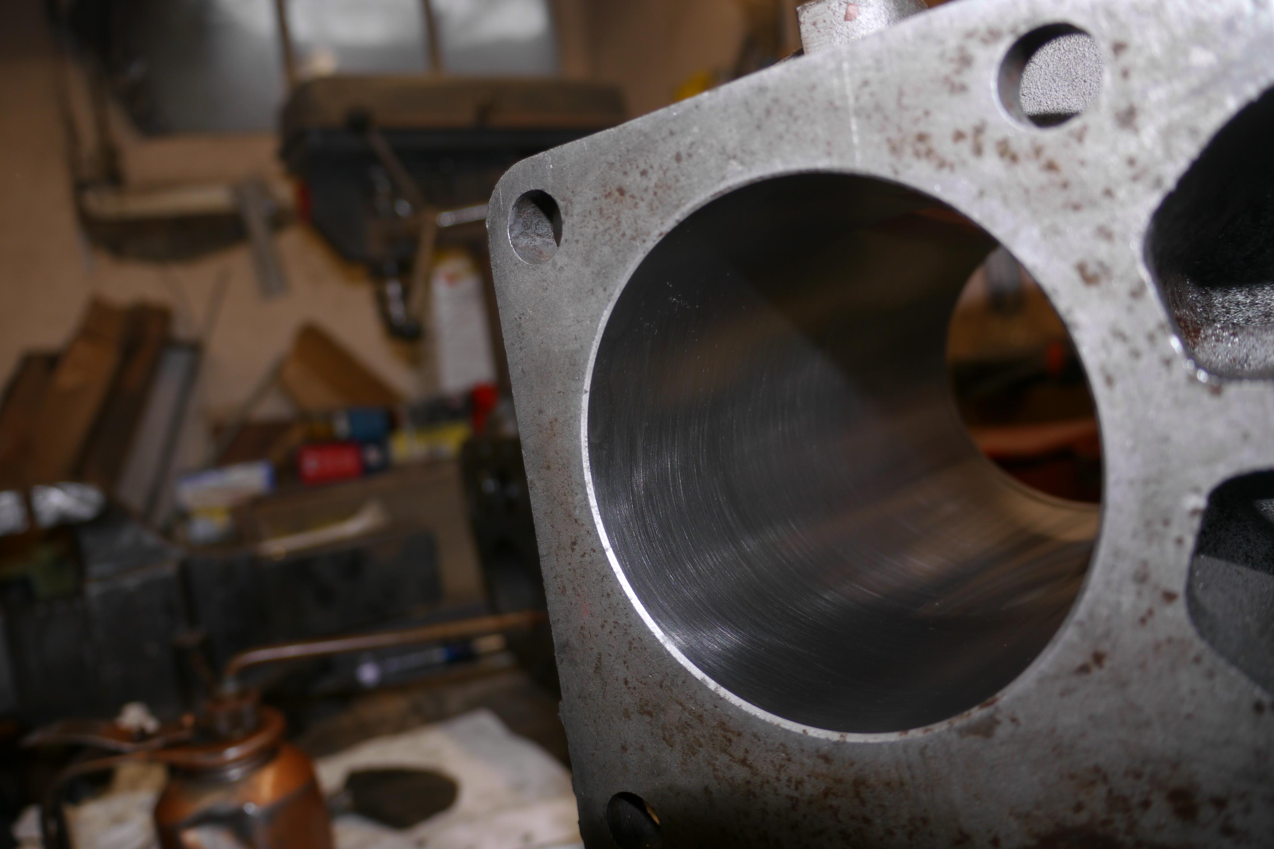
The compressor side cylinder jug was definitely replaced at some point because the cylinder was perfectly round and true from top to bottom. It would be a long shot to think that it wasn’t replaced. Yes the compressor half of the engine will run significantly colder than a conventional engine, but a compressor builds a tremendous amount of heat as well. I wouldn’t be surprised if the compressor side of the engine runs in the 400-500*F range. I decided to re-use the Wisconsin split-skirt pistons on the compressor half of the engine because it was evident that they were also replaced at some point not too long ago. Wisconsin did not manufacture a cam ground piston for the VM4/AFH engines, so I had no choice but to use the split-skirt piston design. There is nothing wrong with the split-skirt piston design, its just not as physically strong as the cam ground pistons. Modern lubricating oil has advanced so far since these engines were produced that the split skirt design no longer makes sense. Wisconsin lists the allowable piston/cylinder clearance of split-skirt pistons to be 0.004-0.005”. With this measurement in mind, I measured up the original cylinders and found just 0.0025” of clearance between the pistons that were fit and the cylinders. I opened up the cylinders just 0.002” in diameter with my hone to have a final piston/cylinder clearance of 0.0035” just under the size mandated by Wisconsin. You might ask why I did not enlarge the cylinders more to have an allowable 0.004” piston to cylinder clearance, and that is because the compressor side is not an engine. Schramm had wanted 0.003”-0.004” of piston to cylinder clearance in the compressor side of the engine. The cylinders on the compressor side of the engine cleaned up just perfectly at finished size. The stones reached the entire scope of the cylinder, ensuring that the new rings will seal sufficiently when the engine is run and broken in. At some point you might have wondered why a torque plate was not used at any point in time when honing. Torque plates are common fixtures used to simulate the cylinder head being fixed to the cylinder. The torque plate ensures that the cylinder is round and true when the head is fastened. This is usually a concern on automobile engines, however in this application Wisconsin only calls for 28-32lb/ft of torque on the cylinder head bolts which is not a really large metric. For how thick these cylinder jugs are and how many bolts are used to secure the cylinder head at a low pull down torque, honing with a torque plate is simply not necessary. Had the cylinder head bolts have been torqued to 75lbs, I would have made up a torque plate to hone the cylinders.
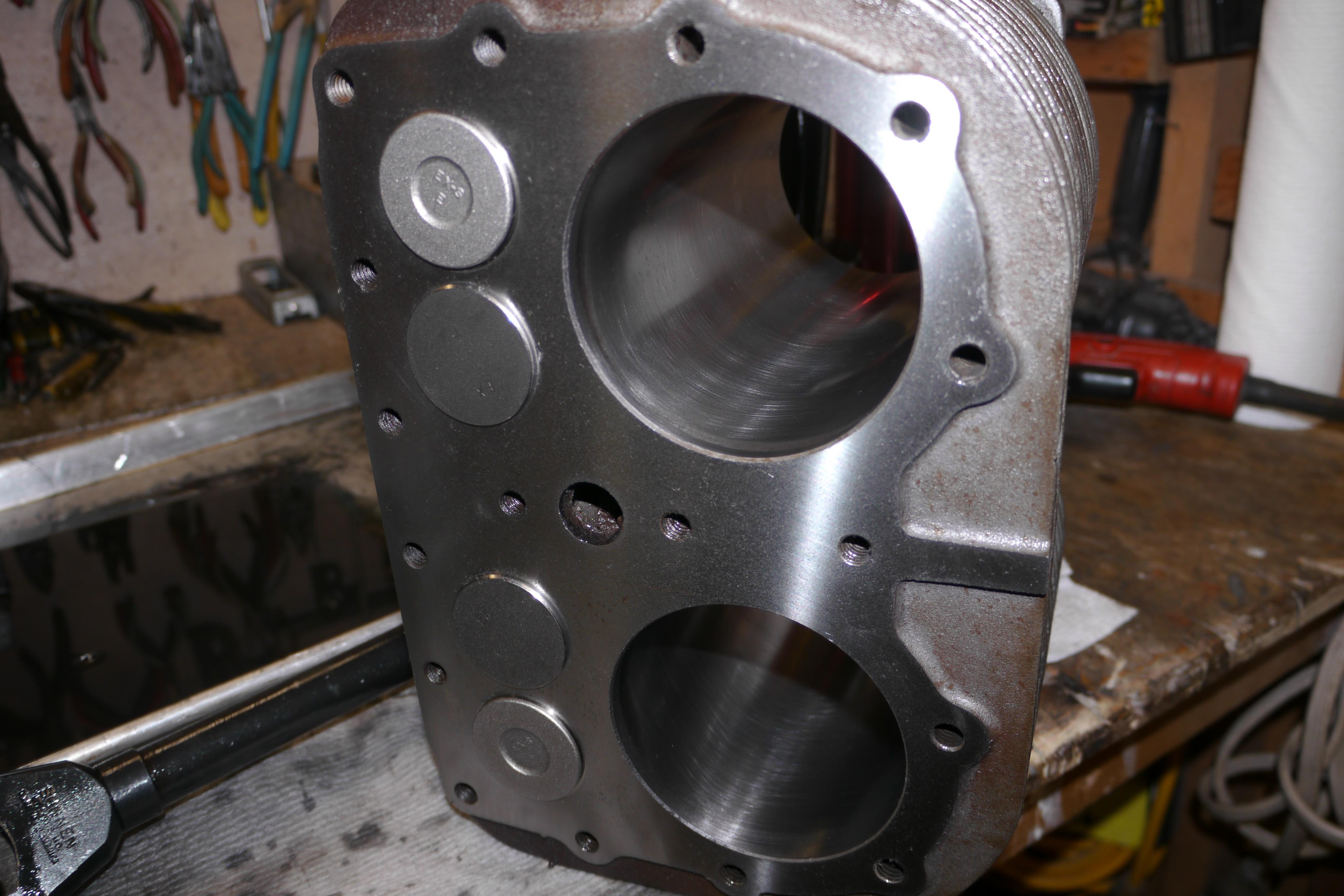
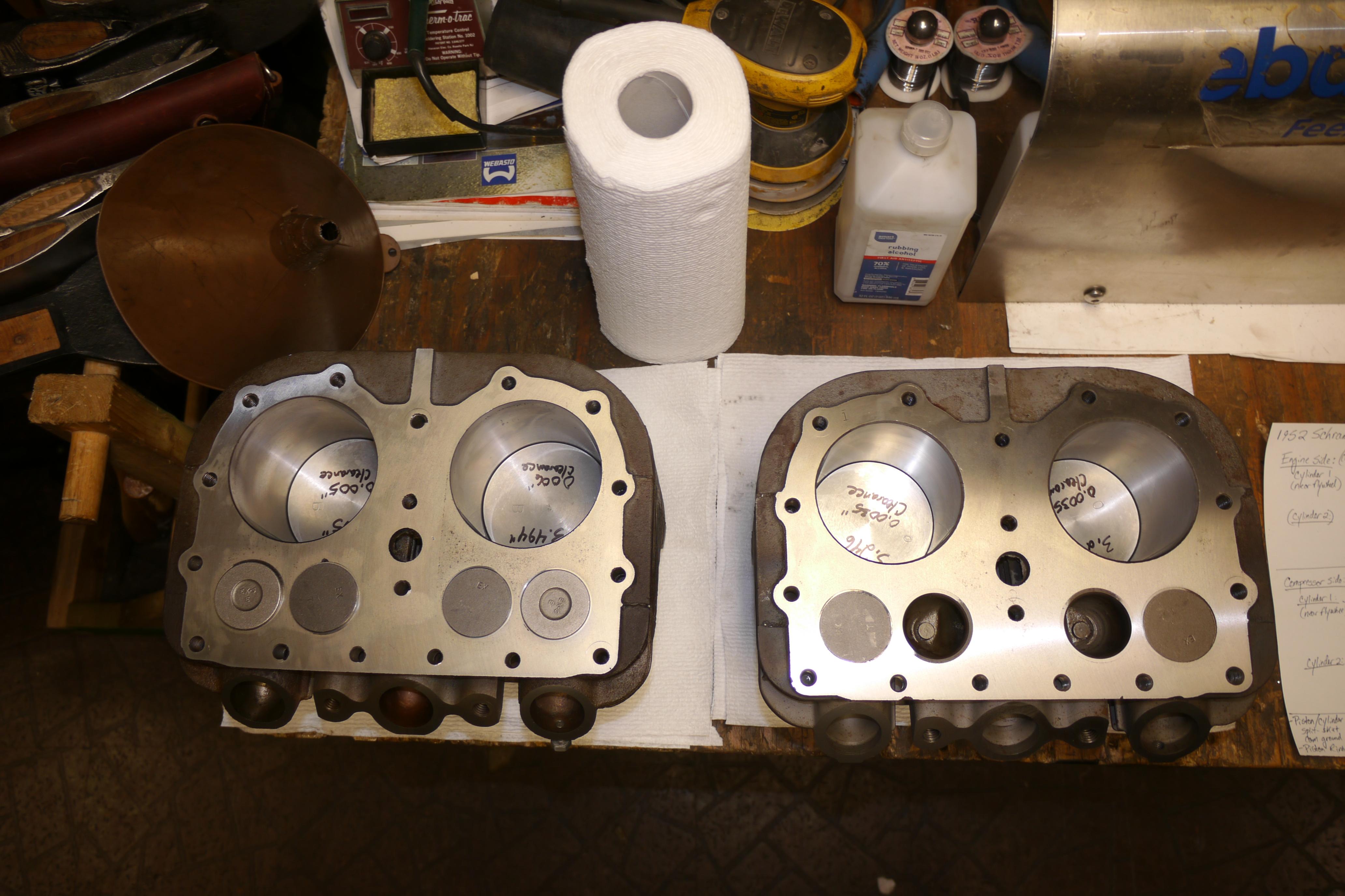
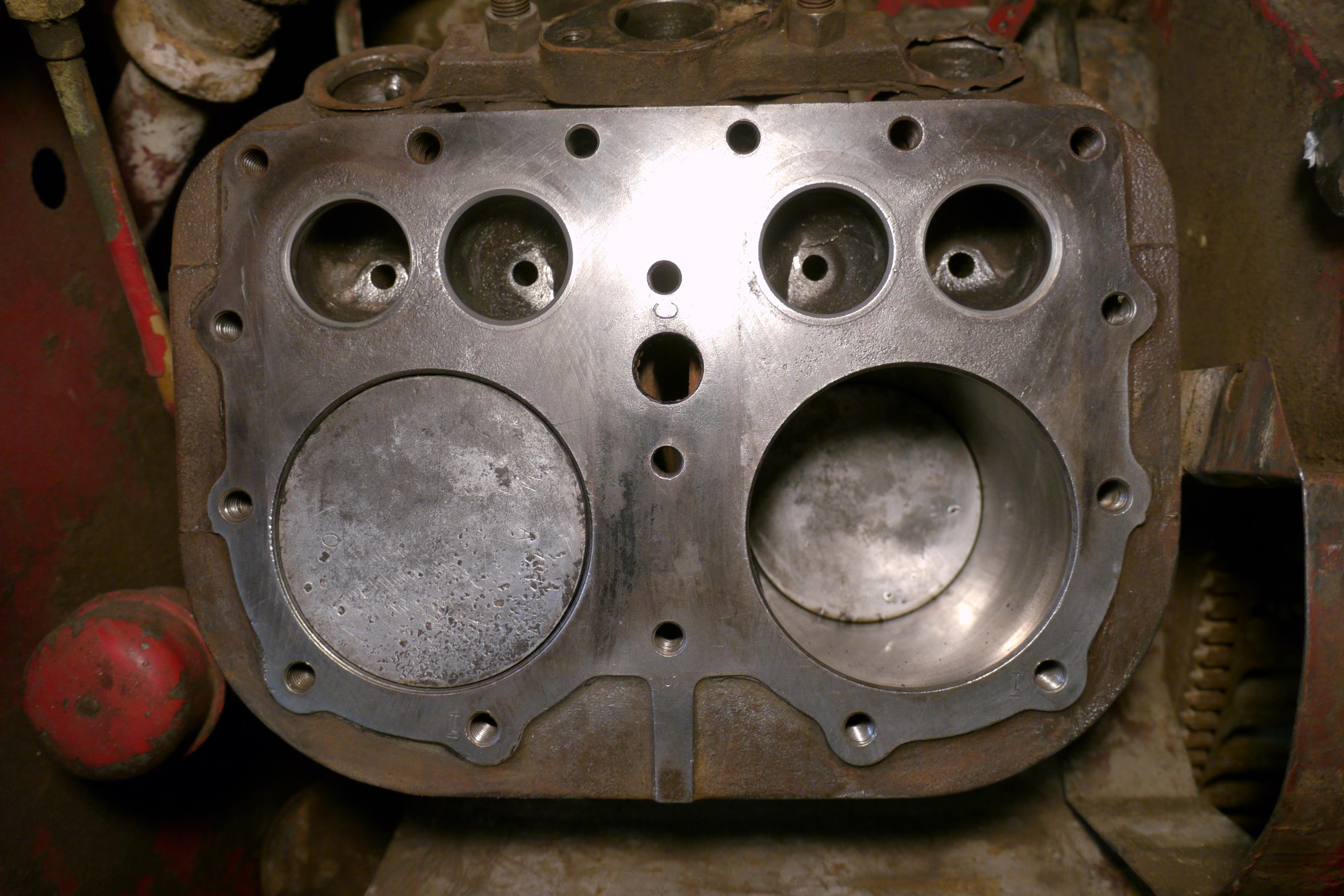
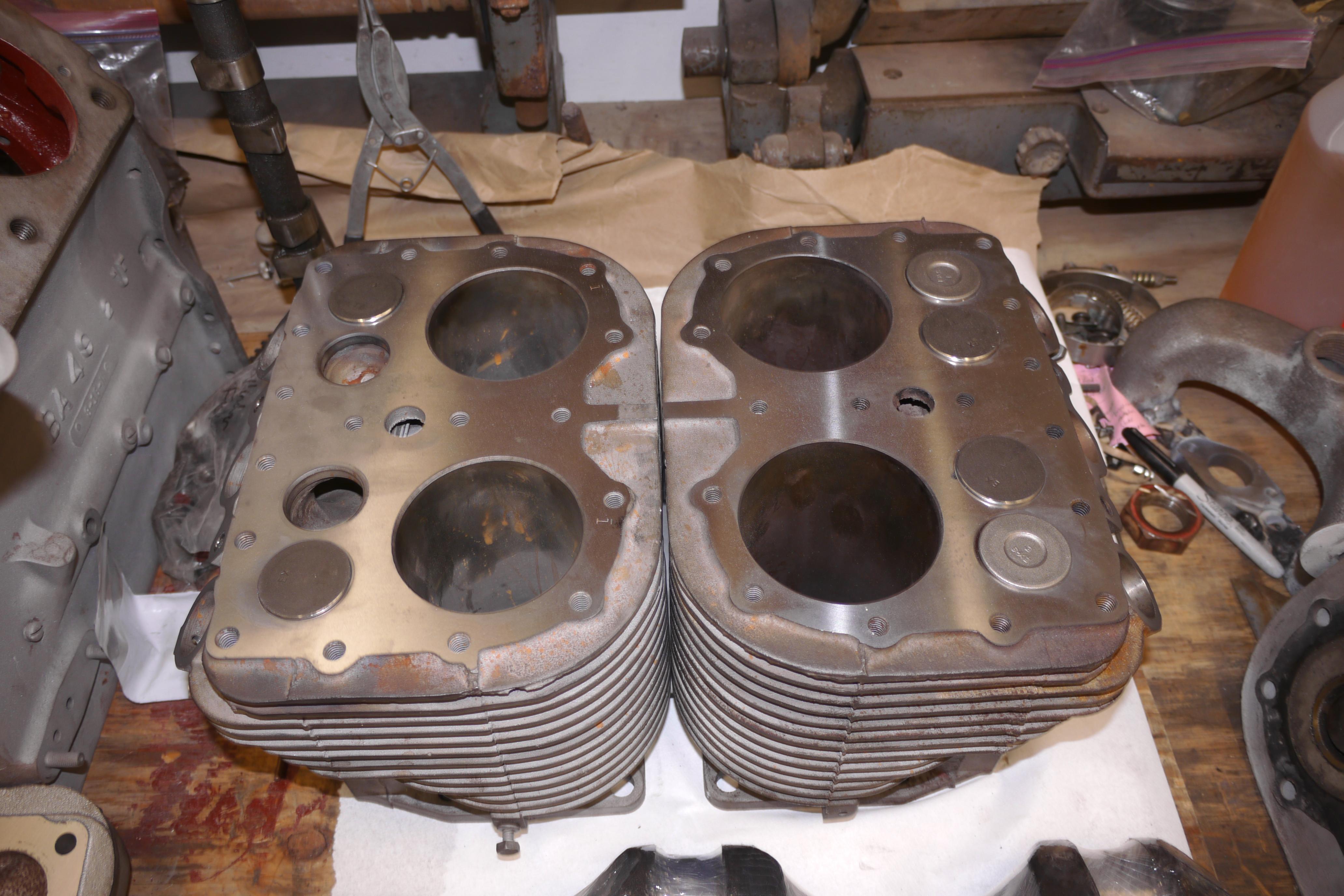
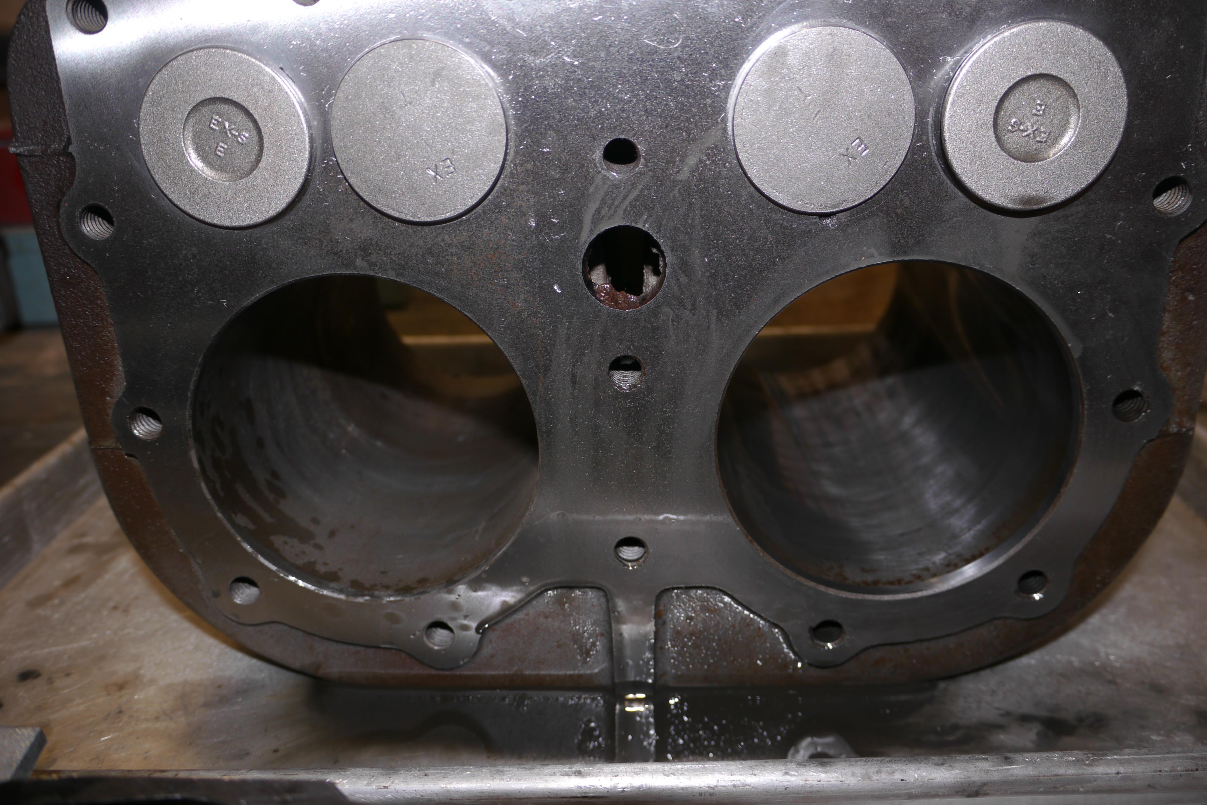
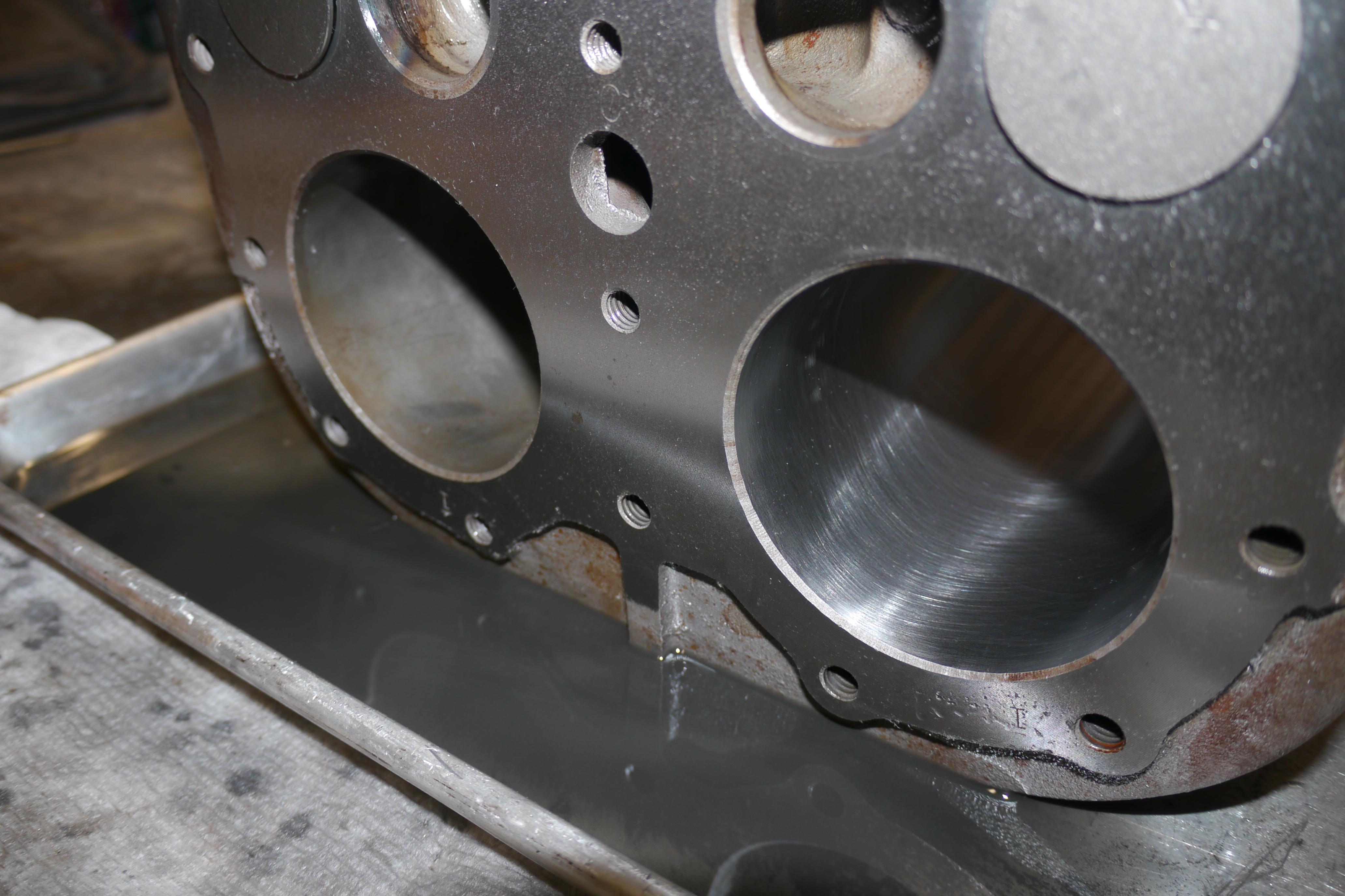
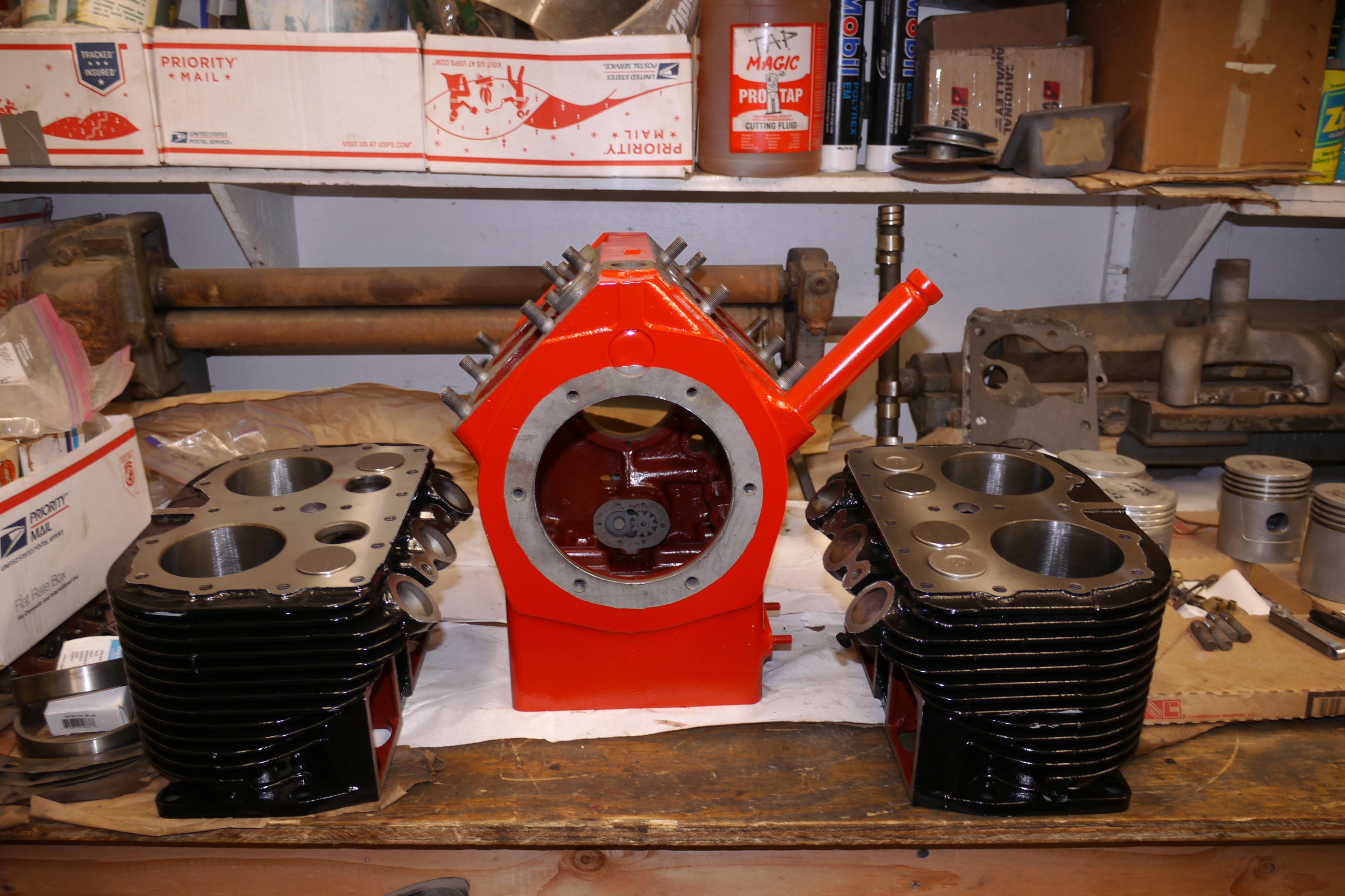
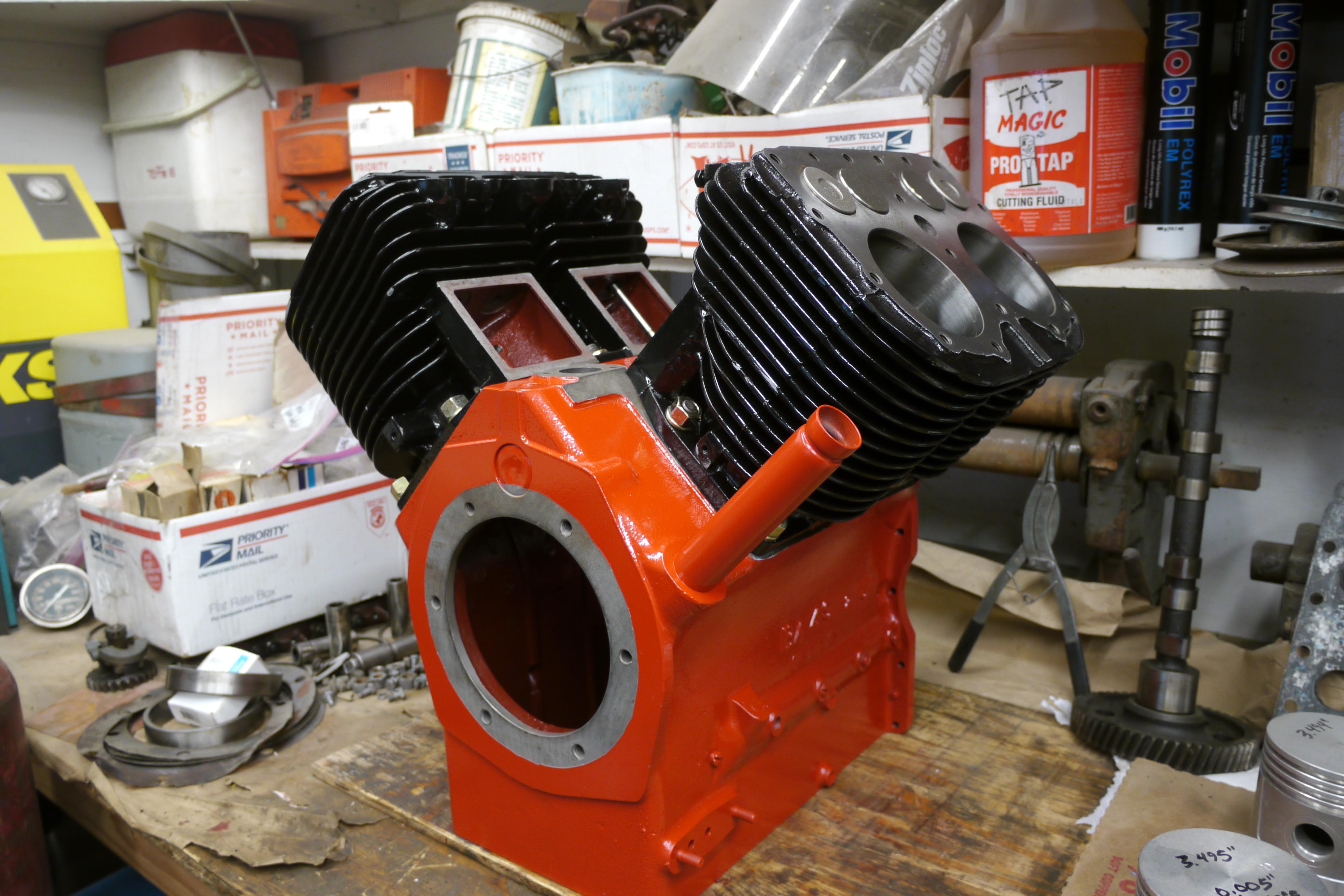
Now that both of the cylinders have been sandblasted, machined for new replaceable valve guides, resurfaced on the top deck and manifold deck, and honed, the engine is finally ready to be put back together. I test fit the cylinder jugs, everything looks great!
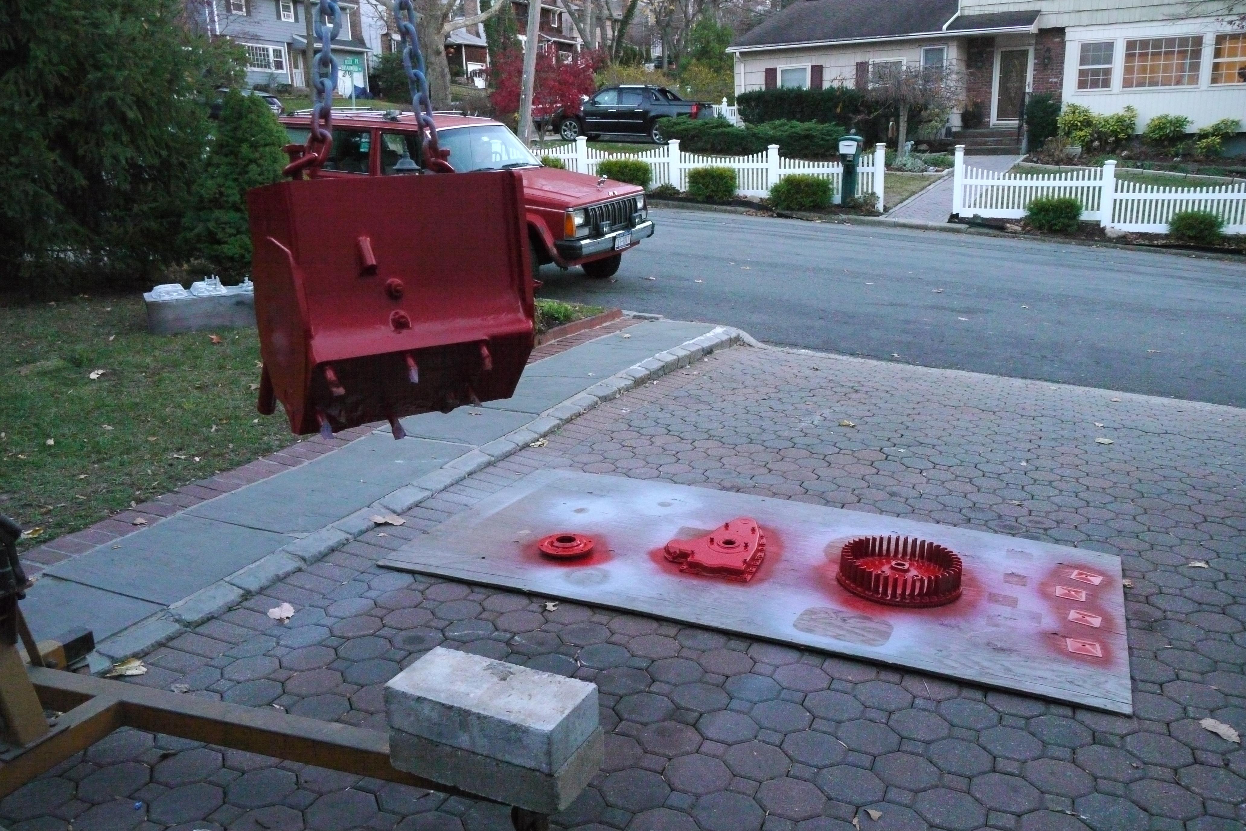
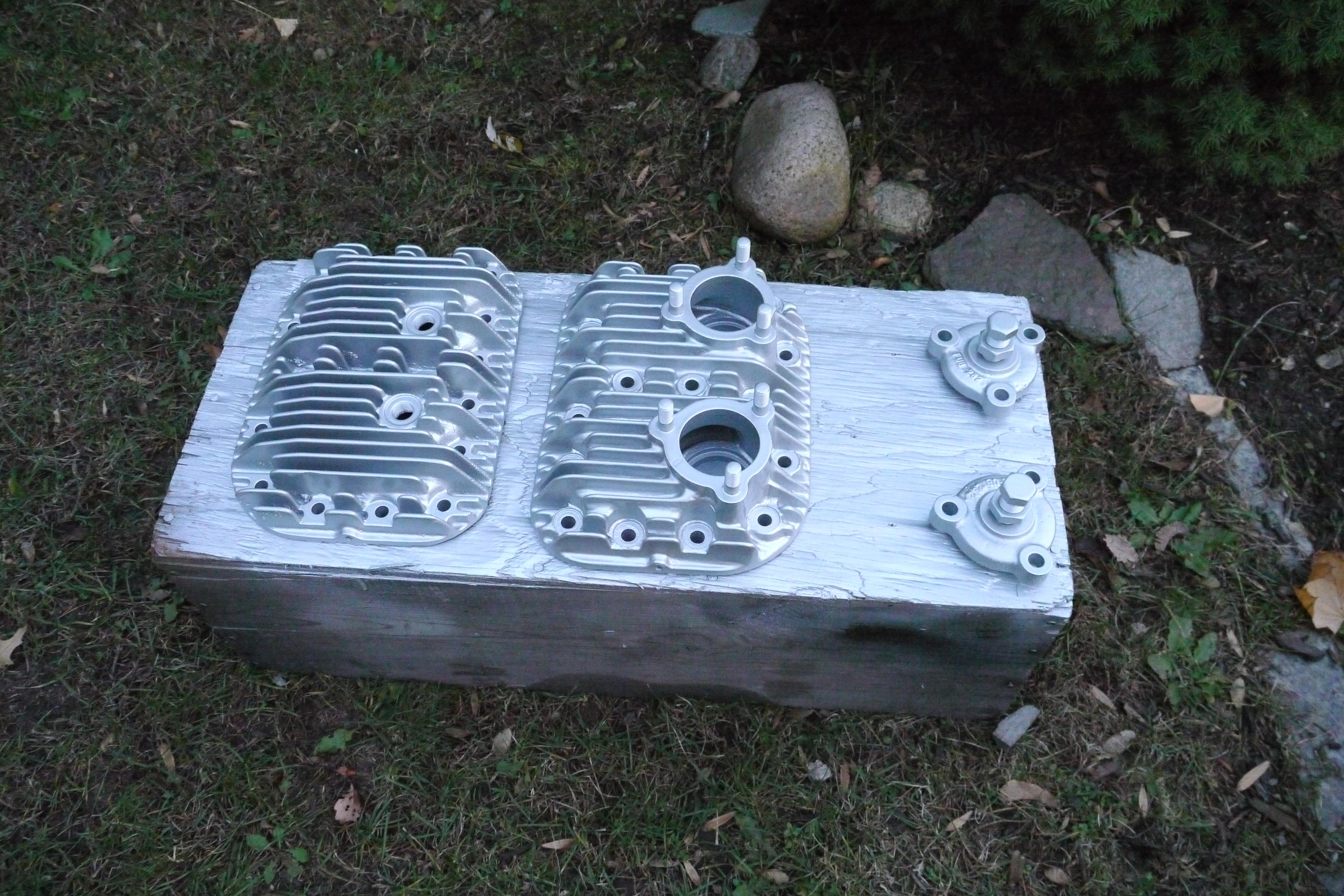
At this time, just about all of the machining work on the engine has been complete, so I took the opportunity to paint all of the sheet metal, the flywheel, the cylinder heads, the cylinder jugs, the crankcase, the oil pump, the governor housing, etc.
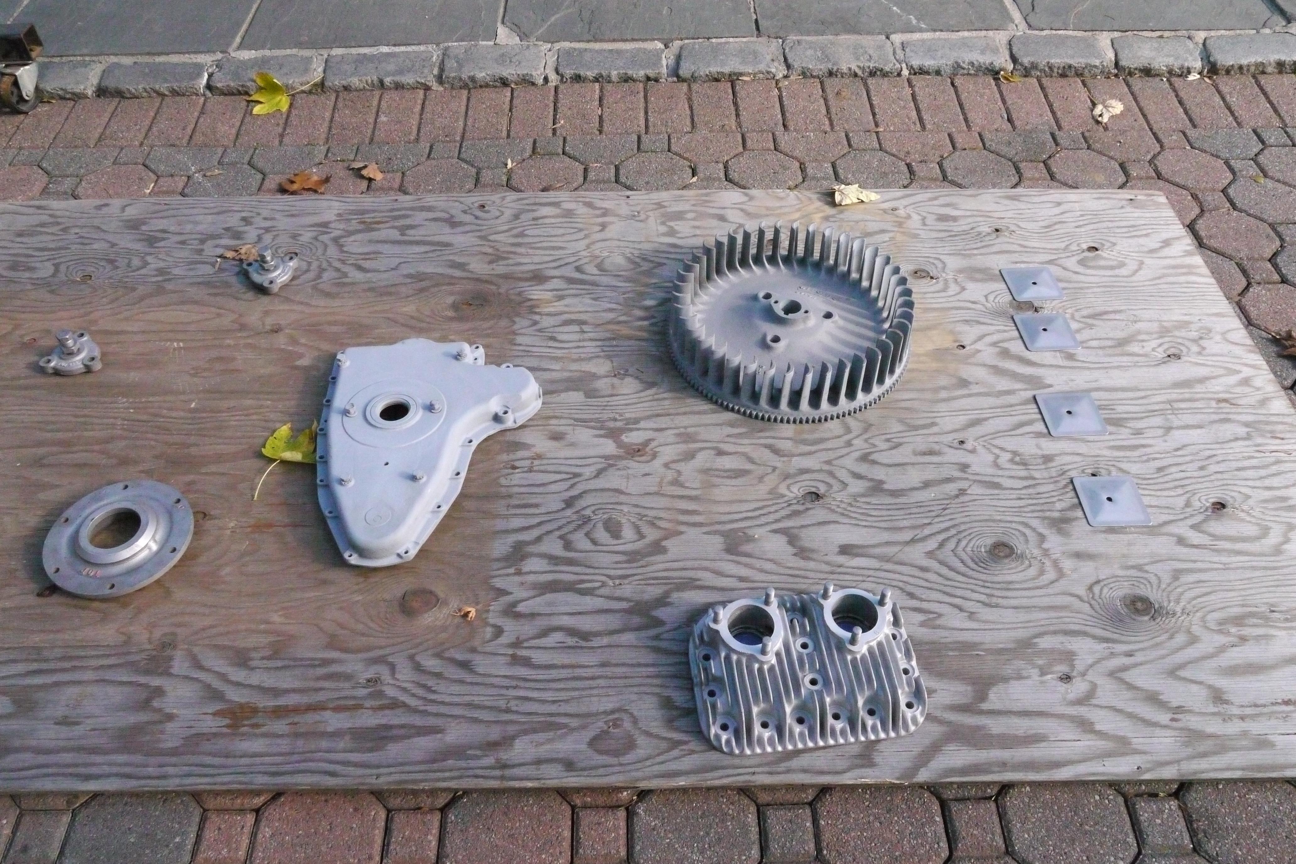
Although Schramm would have painted the entire engine red, I really like the look of black cylinder jugs on a red crankcase, with red tin work and silver cylinder heads. I have been accused of over-restoring engines and machinery, and this is no exception.
With all of the parts painted, I started assembling the engine, when I realized that I did not seal the valve spring pockets with glyptal. I rubbed the bare cast iron down with denatured rubbing alcohol, and let it thoroughly dry before painting the valve pockets with glyptal. Once the glyptal was dry, in roughly four hours, I applied the cylinder to crankcase gaskets, and started assembling the engine.

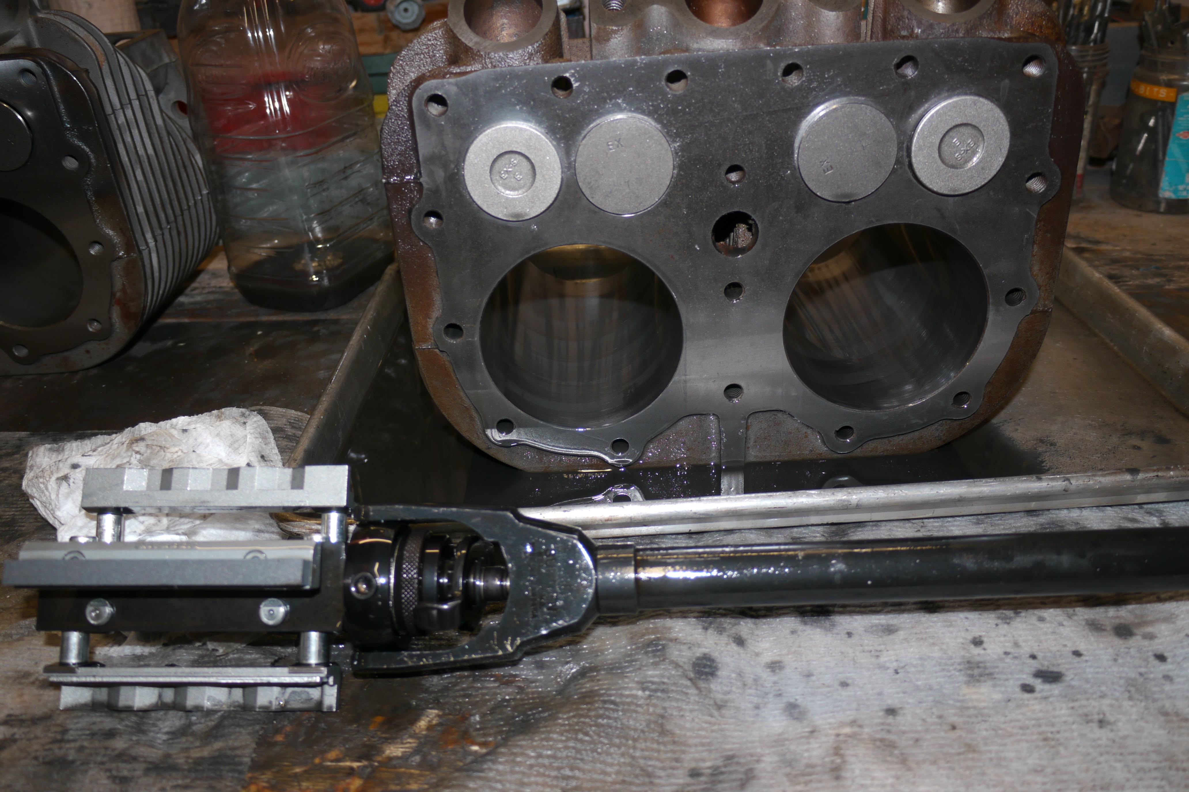
As you can see the cylinder jugs are fastened to the crankcase with six ½-20 studs. I like to use grade 8 hardware whenever possible, and used new nuts and lockwashers to clamp the cylinder jugs to the block. You might ask how it is possible to torque the nuts without the space necessary to swing a ratchet. The answer is simple, I used a crowfoot on my 3/8” digital techwrench. In this case the twelve nuts were torqued to 62lb/ft. When using a crowfoot adapter on a torque wrench it is imperative that the adapter be fitted parallel to the handle of the torque wrench. Because you are effectively increasing the applied leverage arm, you need to calculate how much longer the tool has become. I dropped the torque figure on my tech wrench to 60lb/ft torque, which will compensate for the added adapter.
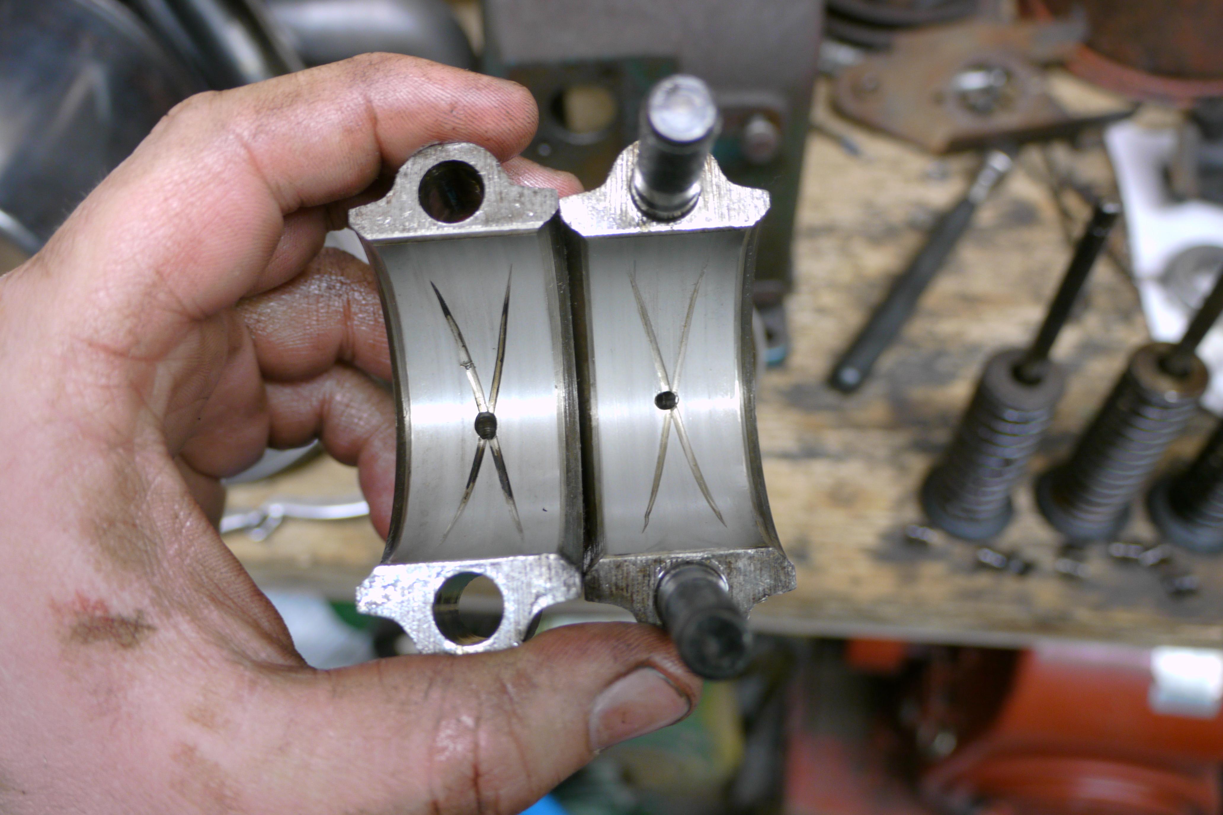
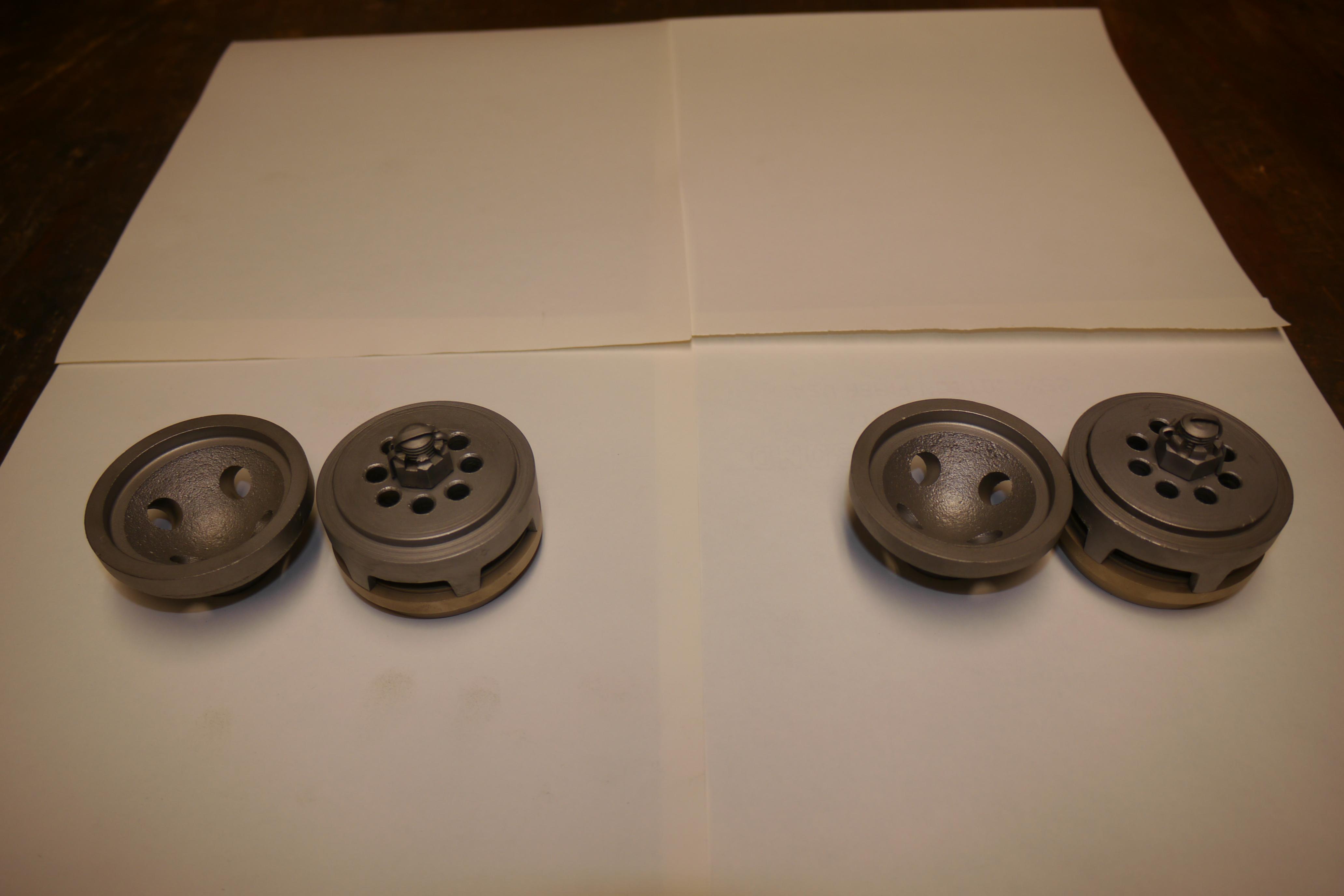
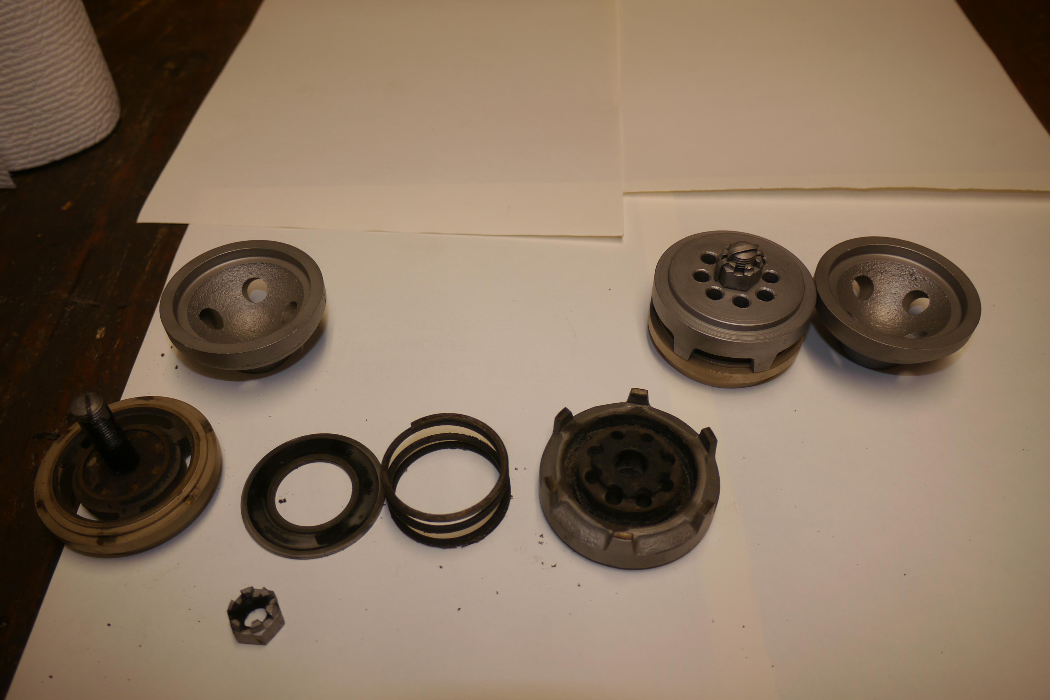
With the shortblock somewhat assembled, I decided to dig a little deeper into the workings of the Schramm unloader valves. For years, Schramm had used virtually the same discharge valve setup, simply scaled from one size compressor to the next. Once you remove the discharge valve cover, fastened to the cylinder head in a triangular manner, you can remove the discharge valve itself.
Upon first glance, the Schramm unloader valves looked very similar to the disc type unloader valves in my 1968 Quincy 230 compressor. Unlike the Quincy, which has a cast iron discharge valve body and bumper, the Schramm has a more substantial cast iron upper housing and a softer brass discharge valve bumper. Here you can see the parts both dirty and sandblasted clean. Residual oil from a reciprocating type compressor is almost inevitable. Maintaining the air cleaner, changing the oil frequently and inspecting the condition of the rings on the piston will reduce down time and oil consumption.
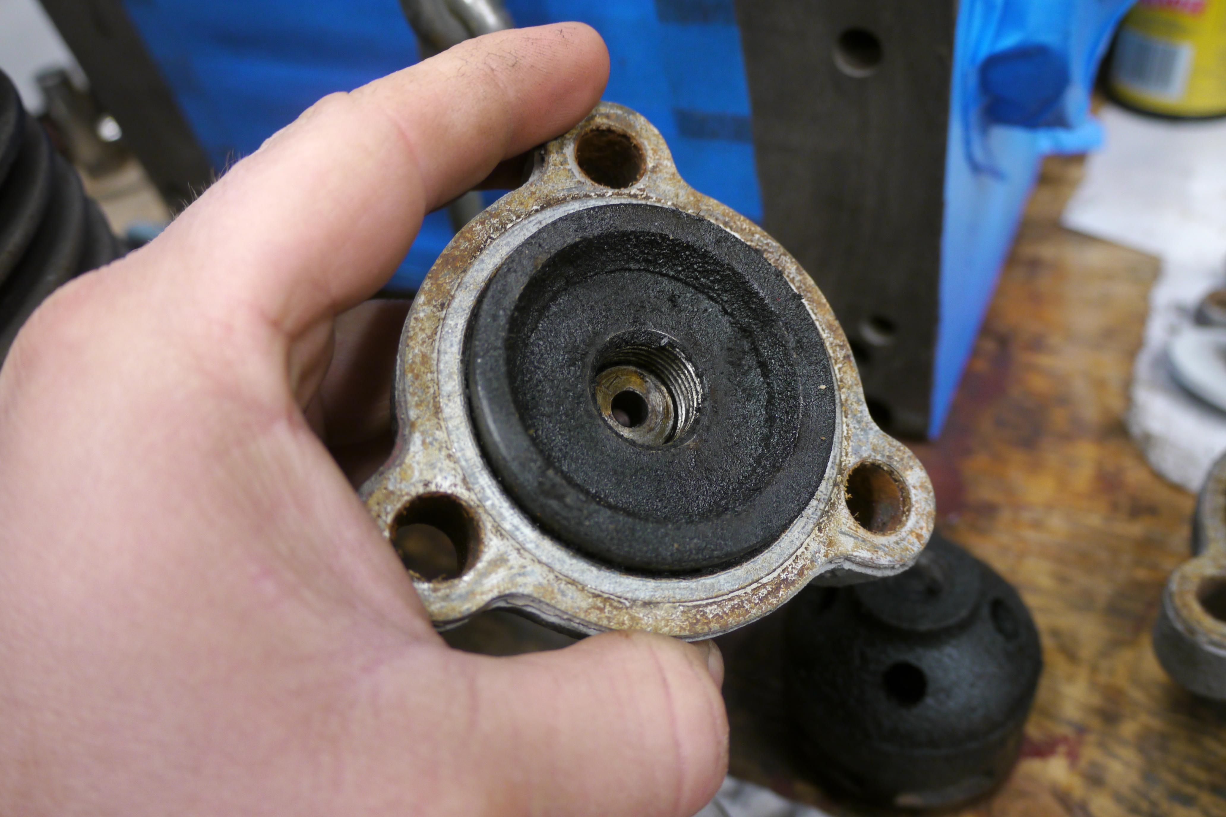
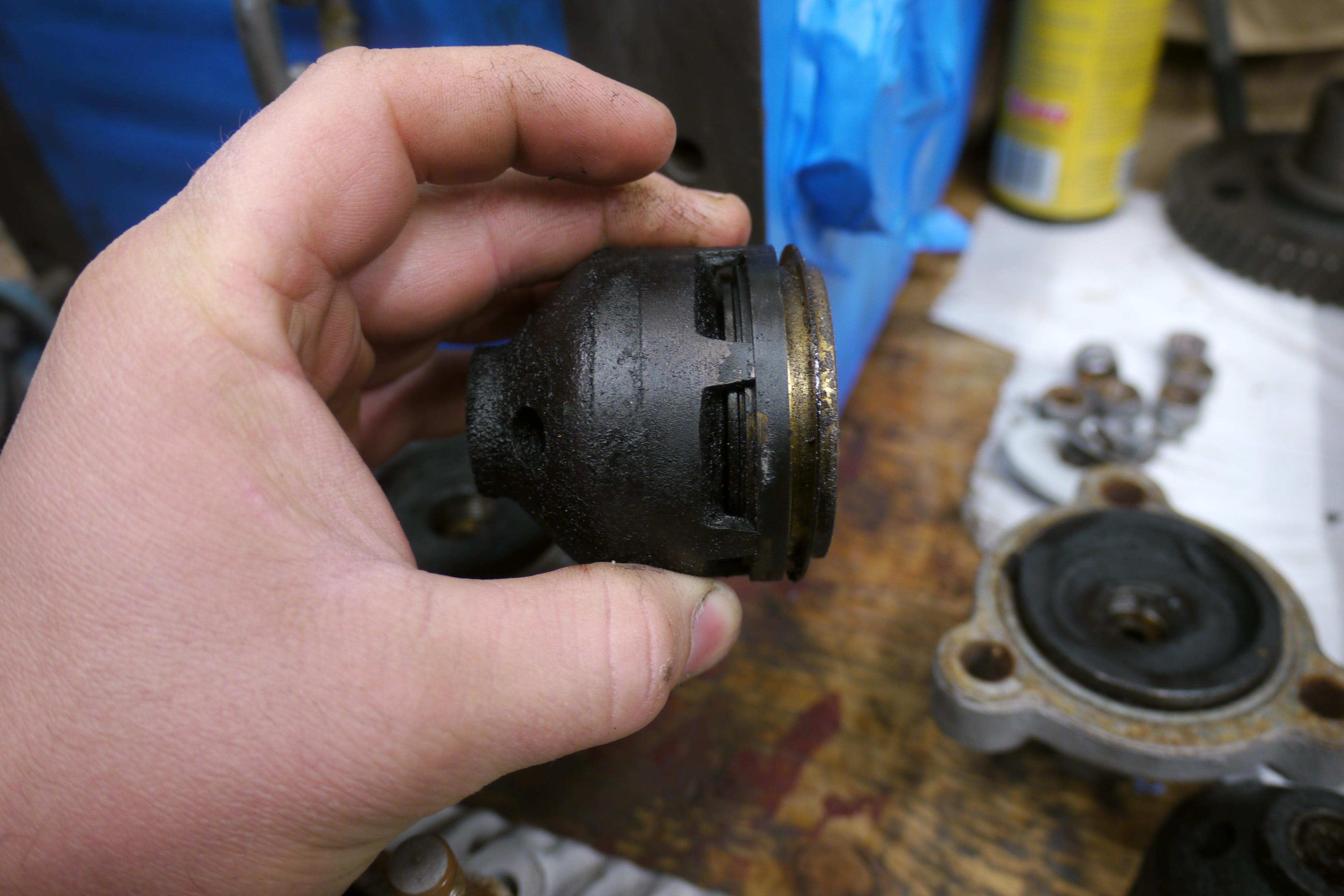
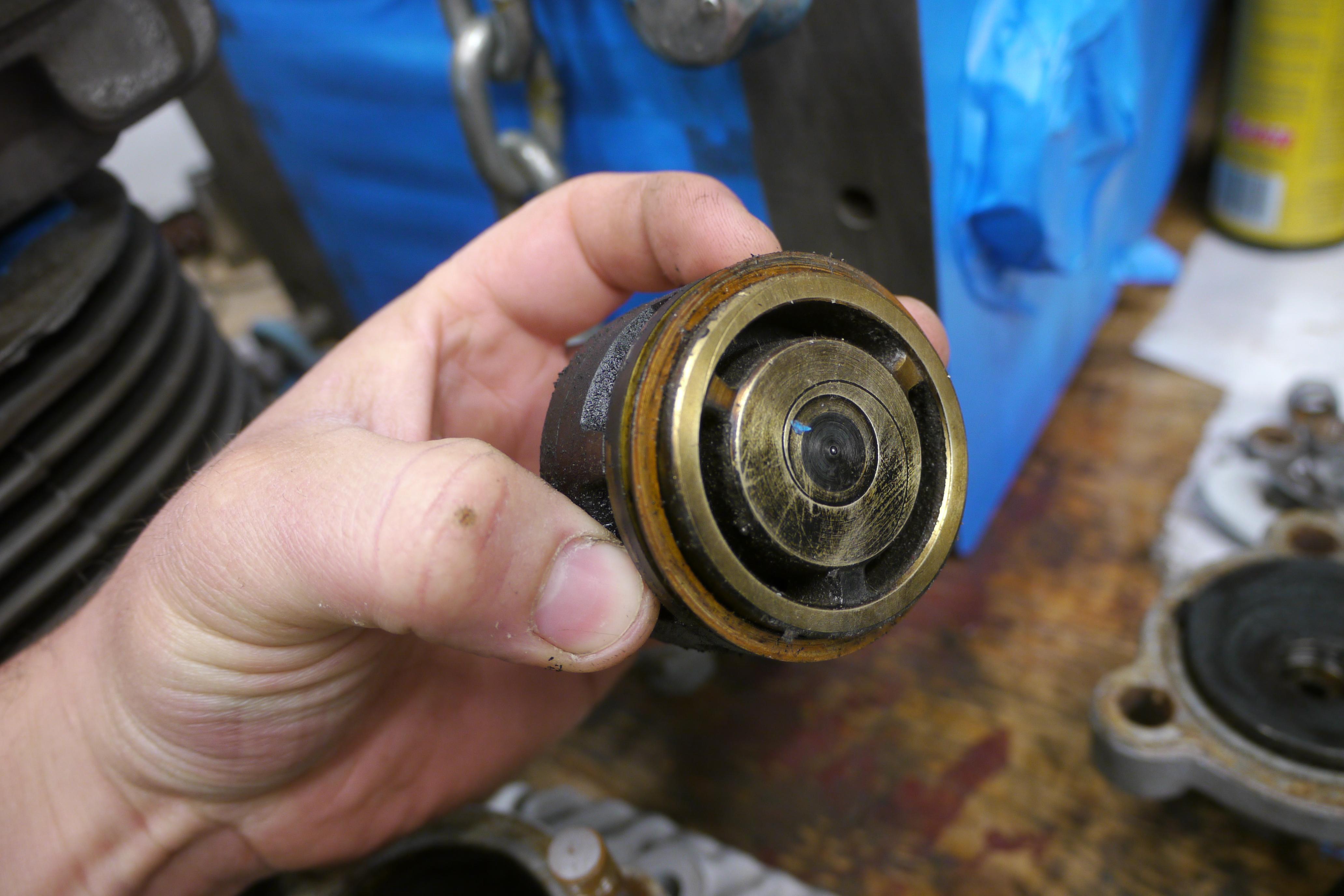
In a similar manner to Quincy, the lower discharge valve bumper is secured to the discharge valve housing by a centralized stud. Here you can see how the discharge valve is assembled. It is of a tri-partite setup, with an upper cap to distribute pressure from the screw on the discharge valve cover to the sides and bottom of the discharge valve for sealing the combustion chamber, the cast iron discharge valve body itself, and then the brass discharge valve bumper. These parts are used and dirty, but the housings themselves will clean up nicely.
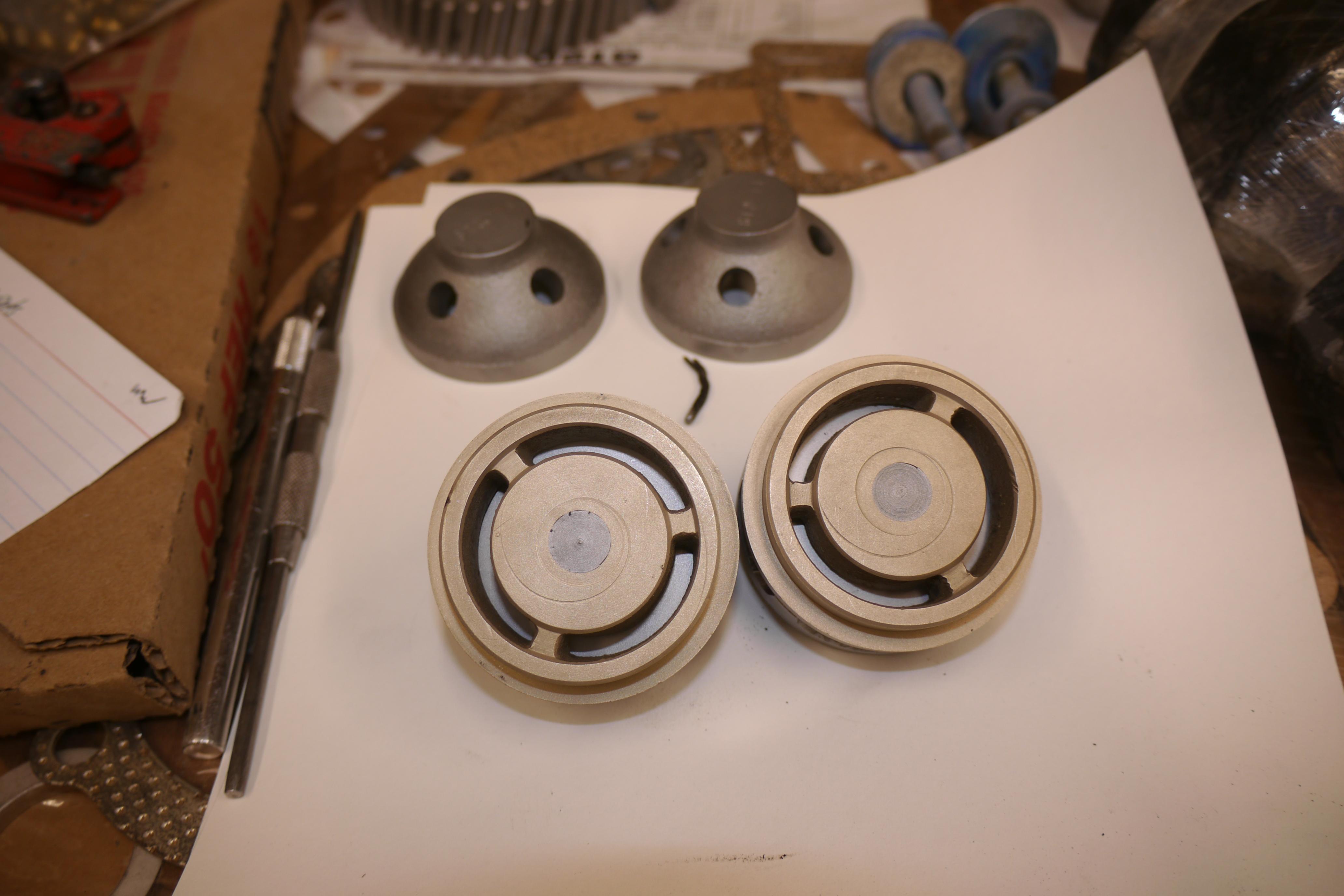
When I was rebuilding my 1968 Quincy Compressor, I had visited our local compressor shop, Scales Compressor in Carle Place. Not only did Mike and Cesar give me the five minute tour of their facility, but Cesar spent some time explaining to me how they recondition discharge valve housings and bumpers. I wanted to include this information here, because it is important to know how to prevent pre-mature discharge valve failure during the rebuilding procedure. Cesar handed me a pick and showed me which surfaces I needed to machine in order to properly rebuild the valve. Over time in a disc type discharge valve, the hardened steel disc itself will begin to wear grooves into the sides of the cast iron discharge valve body. This happens namely because of spring failure, and or an improperly torqued discharge valve body cap. Cesar had told me to use a small deburring tool to remove any lip that a loose discharge valve disc could have worn into the sides of the discharge valve body. The wear occurs on the inside ring of the projected section of the discharge valve body. The discharge valve body has six projections in it to allow and create an area for the pressurized air to escape. As long as the inner face of the projections are cleaned up enough that your fingernail cannot catch, the discharge valve will not catch, chip or fail prematurely. My scribe is pointing to this region here:
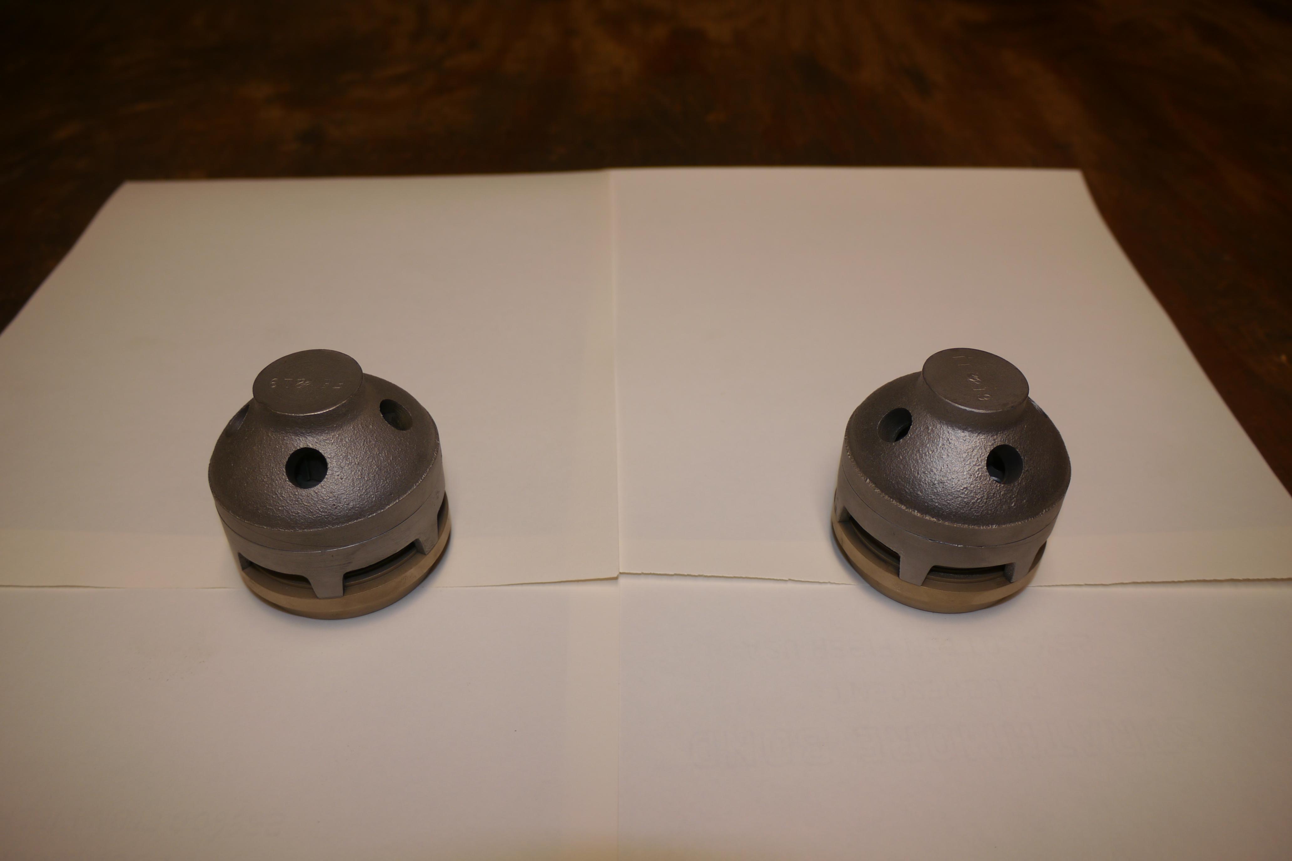
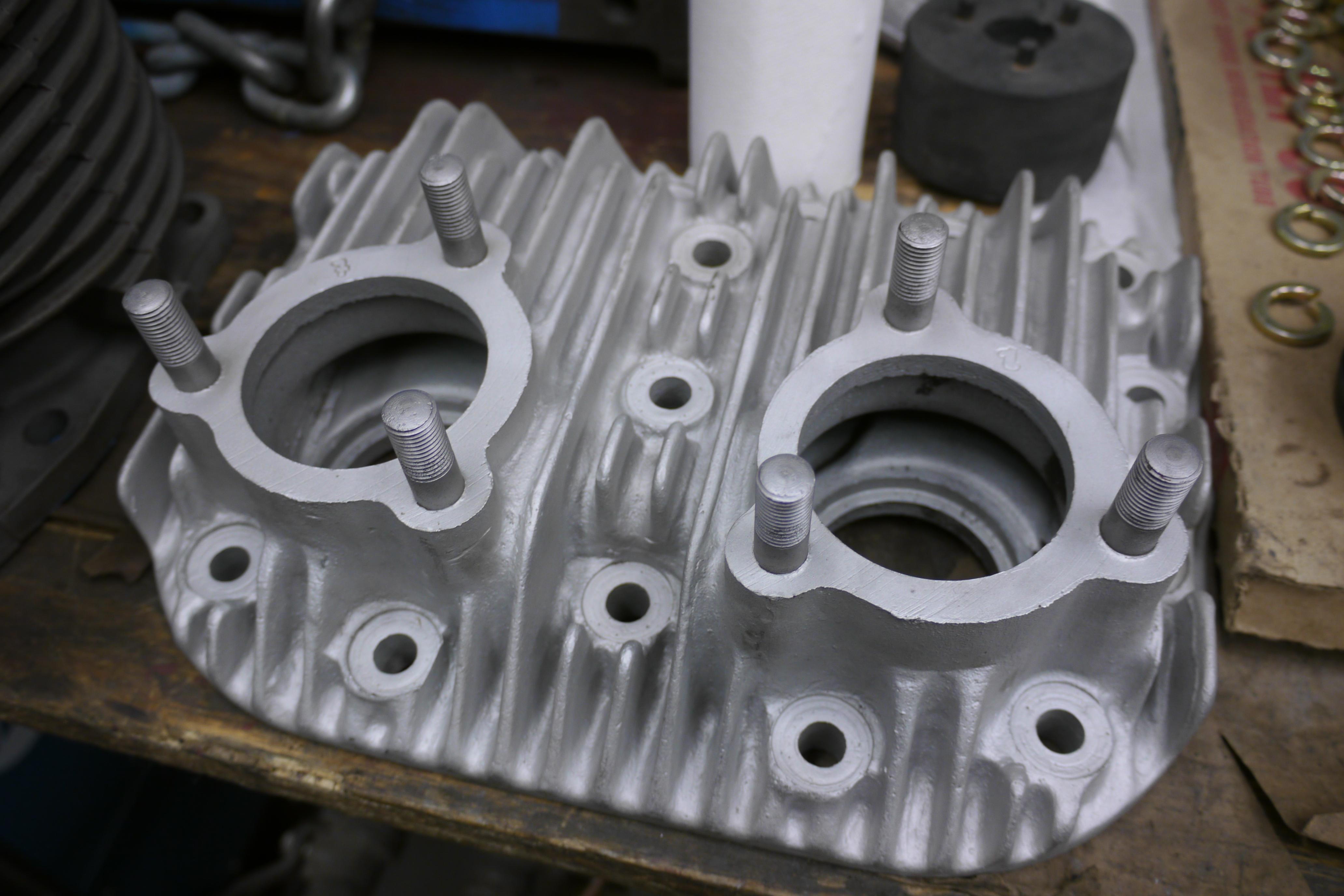
Since Schramm has been out of the compressor business for some time now, I will likely have to source discharge valve springs and discs from a Quincy compressor. The last remaining part of the discharge valve that needs to be addressed is not within the discharge valve at all, but around it. The machined ring in the cylinder head needs to be cleaned and deburred so that the new copper sealing ring will not be compromised when installing the rebuilt discharge valves and discharge valve covers. I actually came across some new old stock copper discharge valve seals at our local town general services shop. They supposedly had one of these compressors a long time ago. I was unfortunately a month too late and a dollar short, they had an entire shelf of new old stock Schramm parts that were scrapped. At least I was able to get an original service manual, and the remaining copper discharge valve sealing rings.
Both discharge valves and the cylinder head for the compressor are thoroughly blasted and ready to go back together.
Further Reading: History of the Schramm Company and the basis of the Pneumapower 35 Schramm Emblem (Picture)
The Schramm Corporation of West Chester Pennsylvania had been manufacturing and converting gasoline and diesel engines into air compressors for nearly fifty years before these two units were made. Christian D. Schramm, owner and founder of the company started manufacturing portable air compressors in 1907 in Philadelphia, Pennsylvania. Christian successfully converted ordinary Domestic hit and miss engines into power absorbing air compressors, which could be driven by electric motors or other hit and miss engines. The #2 and #3 Compressors were some of the first compressors built which weighed 1900 and 2700lbs respectively. In 1912, Christian combined two hit and miss engines side by side to build the model F compressor. The engine was not of his design, but the coupled engine “compressor” was. Together he created the first portable air compressor. As word of his contraption spread parks, quarry’s, highway departments, cemeteries and large construction companies started buying Schramm compressors. Schramm created their own market for portable air compressors to power jackhammers, sandblasters and rock drills. As the demand grew, so did the yearn for larger compressors. In 1917, Schramm built their first multi-cylinder compressor. In 1924 Schramm introduced unloader valves into their lineup of compressors, and in 1933 Schramm released their first diesel engine driven compressor. By the mid 1930’s Christian Schramm and Sons adopted and converted rugged and reliable gasoline and diesel engines into power absorbing compressors. Smaller portable compressors were four and six cylinder engines, with special camshafts, cylinder heads and valve trains operating with half of the engine operating as an air compressor. Larger compressors were factory four and six cylinder engines driving four or six cylinder compressors respectively. Teaming up with Buda, Caterpillar, Continental, Domestic, Ford, Hercules, International, Rock Island, Willy’s and Wisconsin gave Schramm complete control of the air compressor market, and by 1940 they had a compressor lineup from 20 to 420cfm. Schramm’s slogan “Builds ‘Em Better” was born.
Thanks for Reading!
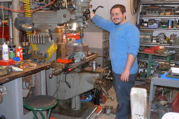
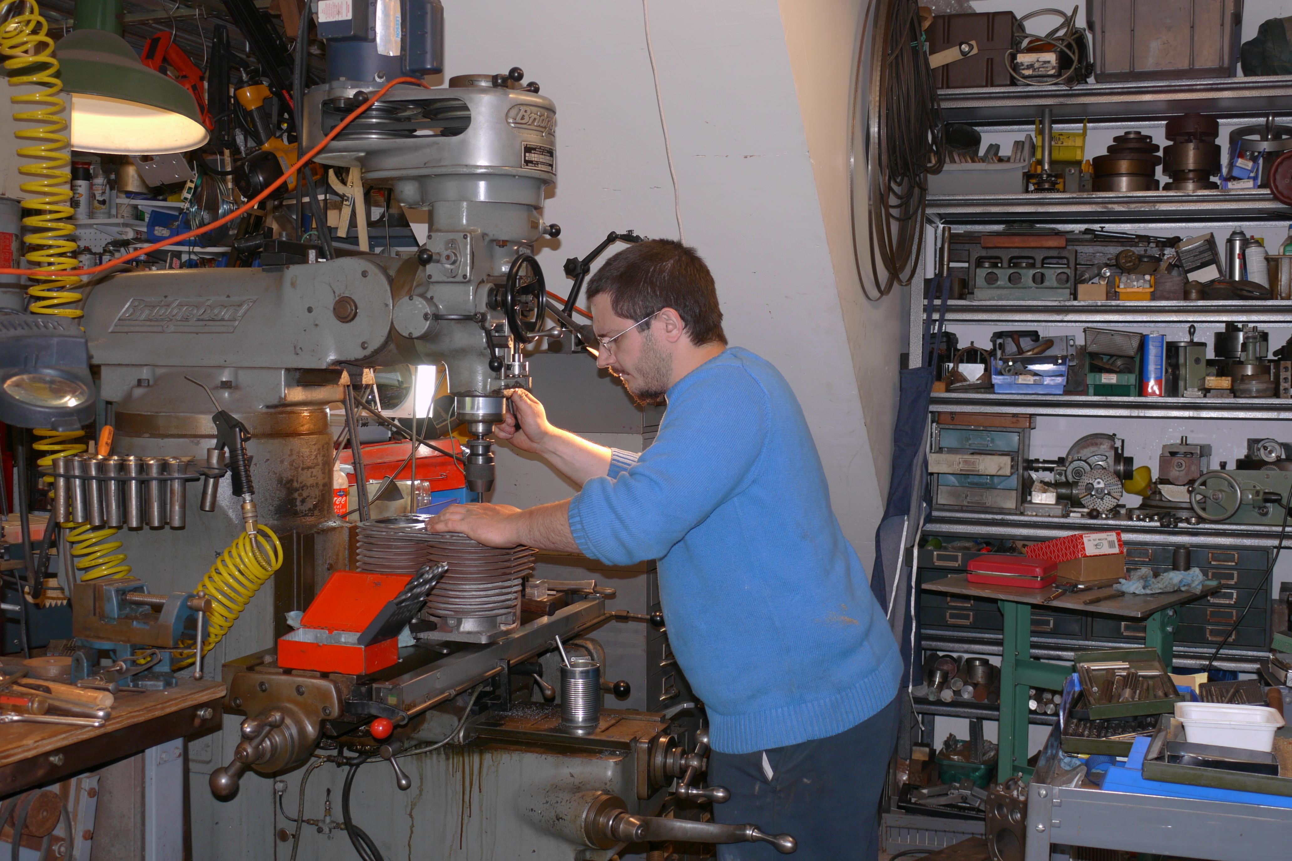
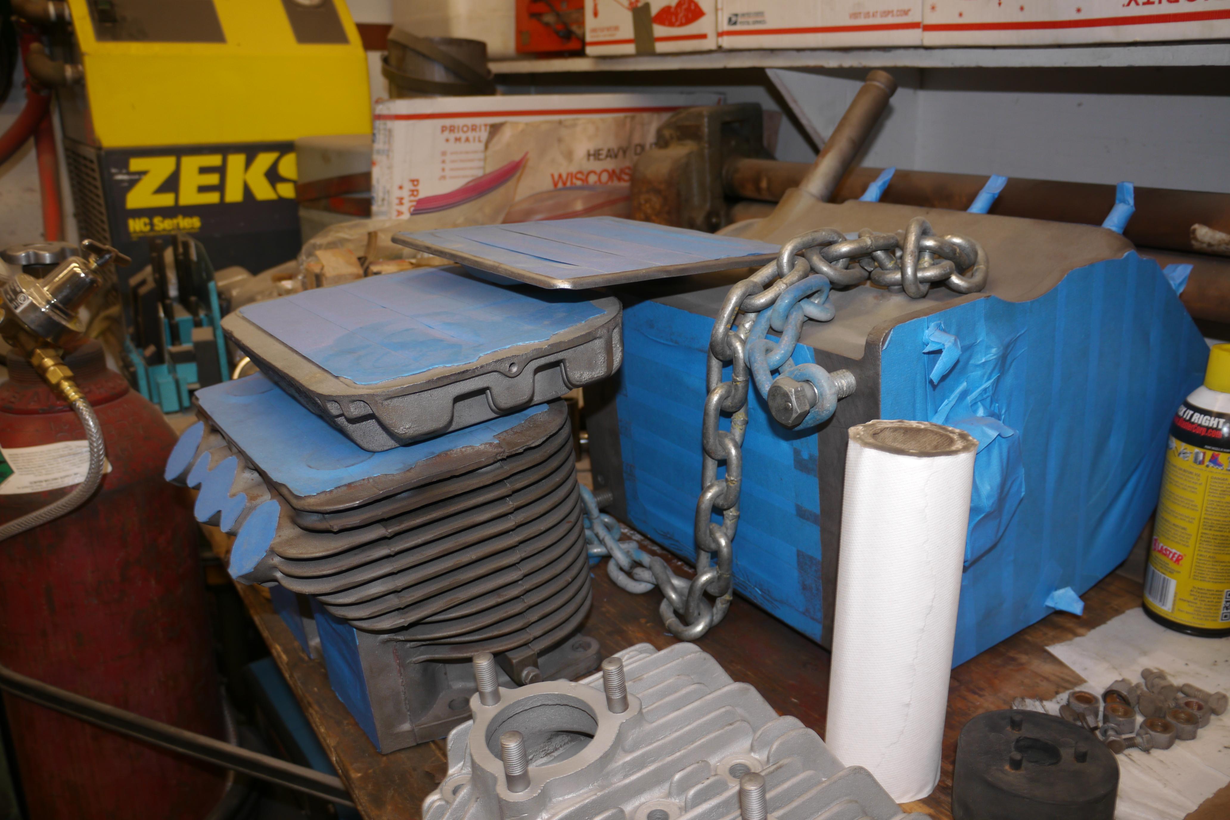
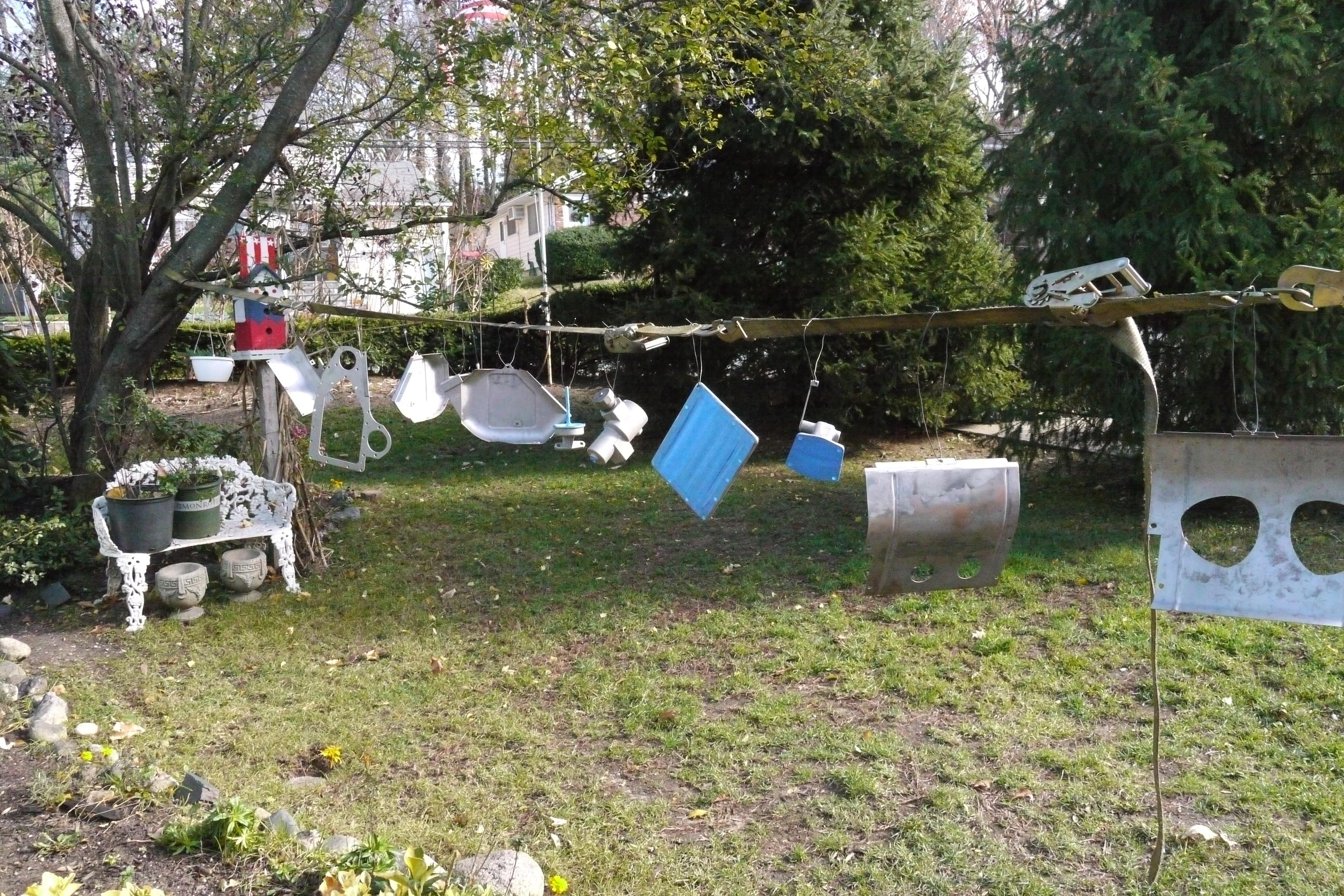
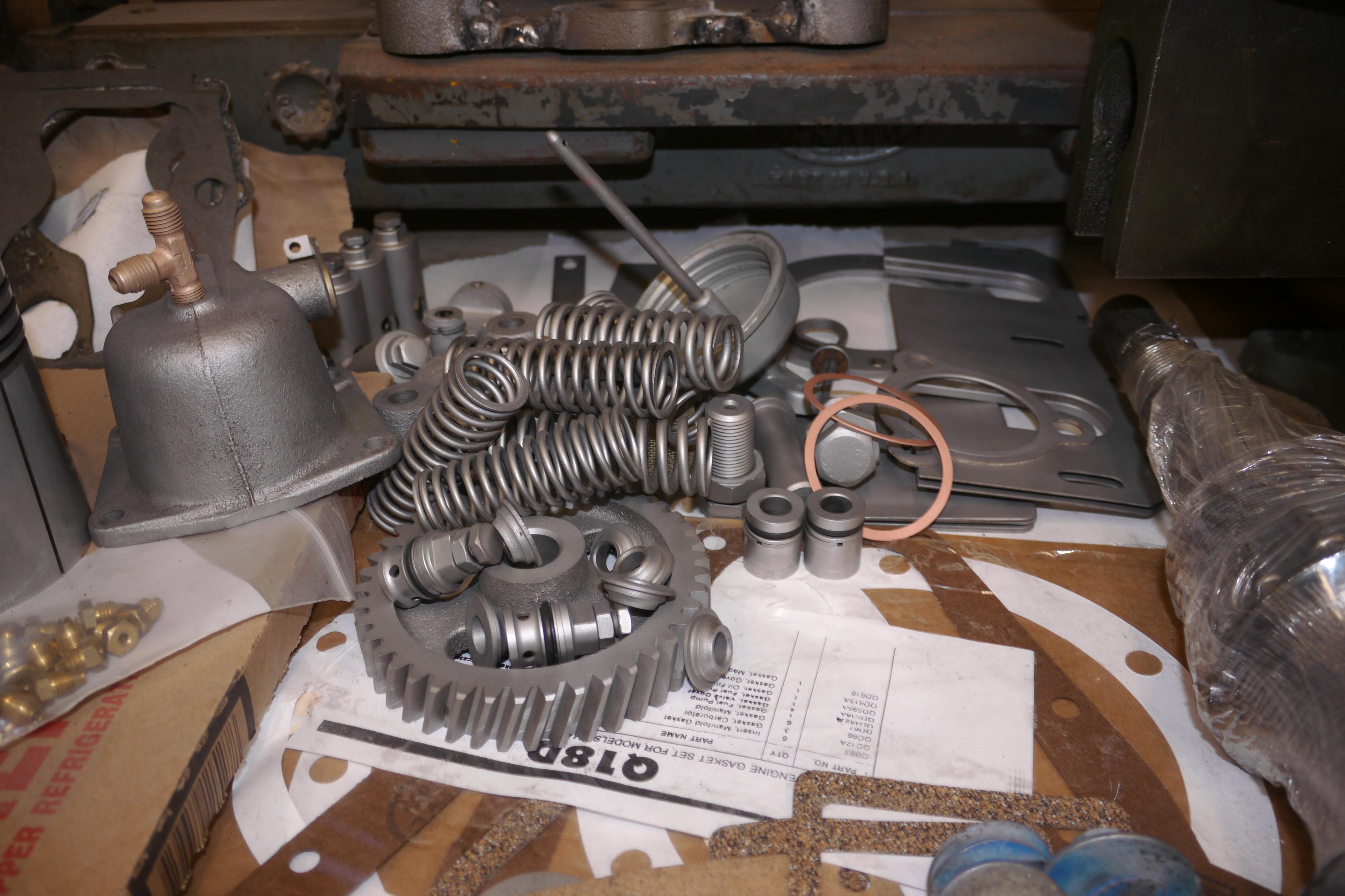
Want more? Here's a behind the scenes look at my workspace and some of the images that did not make the cut to be included in the write-up: